
Home › Forums › Mayfly Data Logger › Voltage divider on multipurpose screw adapter
- This topic has 6 replies, 2 voices, and was last updated 2022-01-14 at 9:25 AM by
 Matt Barney.
-
AuthorPosts
-
-
2022-01-07 at 9:21 AM #16238
I have a question about how to use the voltage divider feature of the EnviroDIY multipurpose screw terminal Grove adapter v1.0.
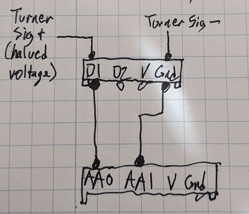
I have a turbidity sensor that outputs analog 0-5V across 2 lines: Signal+ and Signal Ground. (It has separate lines for supply voltage and supply ground.) Using a voltage divider on a breadboard, with a pair of matched resistors, I’ve halved the sensor’s output voltage, then fed that to the Mayfly’s AA0 and AA1, and measured it using the ADC’s differential signaling. All works as expected. See attached schematic.
Now I want to replicate the circuit using a screw terminal adapter, connecting Signal+ and Signal Ground to the screw adapter’s S1 and S2 terminals, respectively.
Here’s what I plan to do: Install the matched resistors in the two positions closest to D1. Set the S1 solder jumper to Res-Div. Leave S2 on Default. Measure the halved output using the Mayfly ADC’s differential signaling between the respective analog Grove pins. Is that the correct way to wire it?
A second question: What’s the best method for removing solder from a solder jumper? I’ve really never used them before, and I haven’t had much luck with my solder sucker. Do you use solder wick? Any tips there would be appreciated.
Thanks,
MattAttachments:
-
2022-01-12 at 5:20 PM #16254
After probing the screw term adapter, I don’t think that it will work for my purposes as I described above. If I’m correct, the way the adapter’s voltage divider works is this: When the S1 jumper is set to Res-Div and two matched resistors are installed on the S1 side of the adapter, the voltage output on the Grove’s D1 pin will be half of the voltage input to screw terminal S1, with Gnd as reference.
However, because my sensor’s output is referenced to its Signal Ground lead, not its Supply Ground, I need to use the ADC’s differential, rather than single-ended, signaling capability. Because of the way the screw terminal adapter maps the output and ground pins, I don’t believe I can use its resister-divider capability for differential signals. Any suggestions? @shicks?
For reference, the sensor’s wiring guide is here: http://docs.turnerdesigns.com/t2/doc/manuals/998-2188.pdf
Thanks,
Matt
-
2022-01-13 at 11:45 AM #16256
Hi Matt, sorry I didn’t see your original post from last week. You are correct in how the resistor divider works, we have several sensors that have a 0-5v DC output, so dividing it in half makes it safe to read with the 3.3v-based circuitry of the Mayfly’s ADS1115. However, you can also use mismatched resistors to create a divider for something like a 0-12v signal too.
Are you sure you need to use differential measurement of the sensor analog output? Many analog-out sensors have separate power and signal ground lines, but sometimes the manufacturer says it’s okay to connect the signal and power ground wires to the same point. If that’s the case, then you can use the screw terminal board as it was designed by changing over one of the solder jumpers (like JP1) and adding matched resistors to R1 and R2. I haven’t used that particular Turner turbidity sensor, but all of the other Turner sensors I’ve used have allowed me to connect signal ground to power ground.
But if you’re sure you need to use differential measurement, then there’s no easy way to use the screw terminal board since the divider circuitry is based on using the ground pin from the Mayfly as the common wire for the divider. You could modify your board by either cutting traces or by hacking/splicing the Grove cable between the screw terminal board and the Mayfly and adjust which wires go to where, but using a common ground would be a much simpler approach if that will work with your sensor.
-
2022-01-13 at 1:06 PM #16257
Thanks Shannon. I’m not positive that I need to use differential measurement… I’m approaching the edge of my knowledge as a non-EE. Turner doesn’t specify whether it’s OK to connect signal and power grounds to the same point — maybe I’ll ask their tech support. But when the sensor is on, I’m measuring around 13 mV between its signal ground and power supply ground wires. Thus when I read the measured value (voltage) across Sig+ to Sig-, it’s different than if I read voltage across Sig+ to Supply-.
I just now modified a Grove cable by disconnecting the V and Gnd lines and moving the Signal Ground so that it will connect appropriately to the ADC (see ugly drawing attached), and will test it today. I found it pretty easy to disconnect individual wires from a Grove connector, using a dental pick, so I may just go that route.
Matt
Attachments:
-
2022-01-13 at 3:12 PM #16259
FYI, Turner tech support tells me that Signal Ground and Supply Ground must be “Kept separate so that noise isn’t injected into the response.”
-
2022-01-13 at 9:44 PM #16260
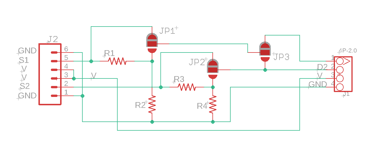
Sounds like modifying your Grove cable to connect the resistor pair to your differential input is your best bet. Here’s a schematic of the multi-purpose screw terminal board if that helps. The gray area on the 3 solder jumpers in the schematic shows the default position of the jumpers. If you’re putting resistors in R1 and R2, you’ll want to change JP1 to the res-div setting. Were you successful at moving the solder blob?
Attachments:
-
2022-01-14 at 9:25 AM #16262
Thanks for the schematic – that is helpful. I removed the solder blob using solder wick and re-added it to the res-div position, but it wasn’t pretty; it looks like I overheated the board a bit, but it still works. Later, I found a different technique in this video, which I’ll share here for anyone else who needs it.
-
-
AuthorPosts

- You must be logged in to reply to this topic.