
Home › Forums › Other Data Loggers › Serial datalogger RS485
Tagged: binary, datalogger, serial
- This topic has 4 replies, 2 voices, and was last updated 2019-10-08 at 11:31 AM by
ggraves.
-
AuthorPosts
-
-
2019-10-01 at 9:35 PM #13192
Hi all,
I’m am attempting to hook up an acoustic Doppler current profiler to the mayfly logger to output binary data via RS485 serial (RX0/TXO) as half duplex, 8 bit no parity no stop. Any suggestions on how to go about this? The data output is in this format here: rowetech binary: http://rowetechinc.co/wiki/index.php?title=ADCP_Data_Types
I’m basically looking for a way to capture the output in raw format to a text file as one long string for post processing in another software.
Thanks!
-
2019-10-02 at 5:27 PM #13195
You’ll need an RS485 to 3.3V TTL adapter. I *strongly* recommend getting one with built-in flow control. I also highly recommend hooking your doppler up to the Mayfly’s Serial1 unless you have good reason not to.
Once you have the connector you should be able to transfer data from the doppler to an SD card using a library like SdFat and a simple sequence like:
while (Serial1.available())
{
SdFile.print(Serial1.read());
} -
2019-10-03 at 4:17 PM #13205
Hi Sara,
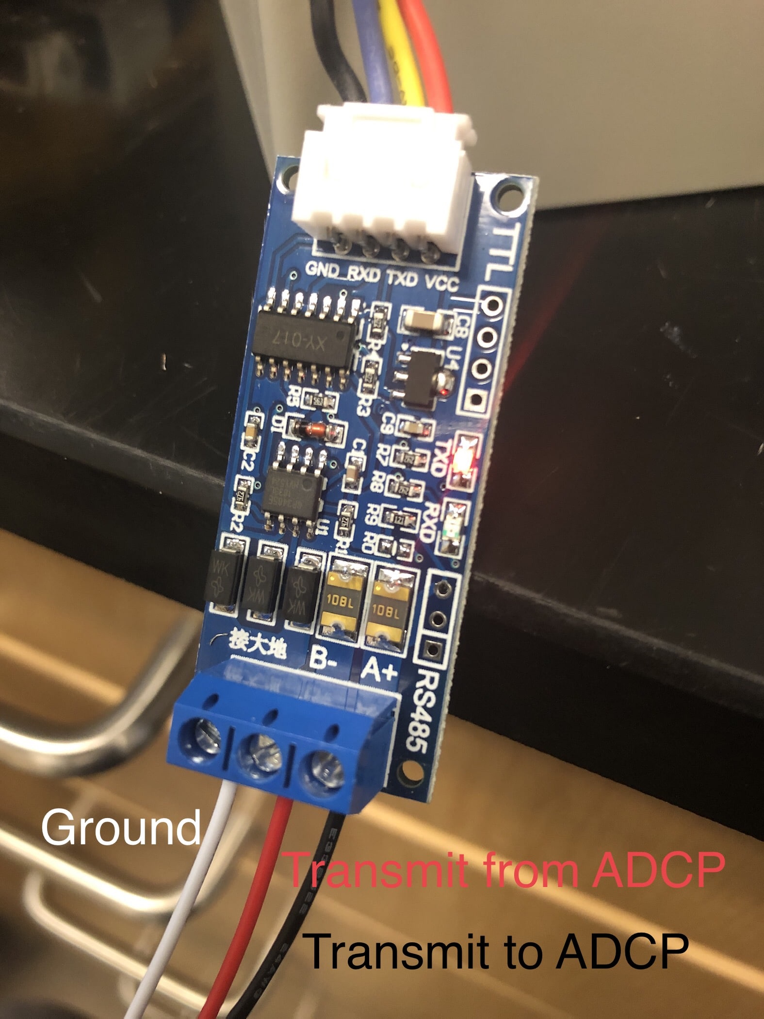
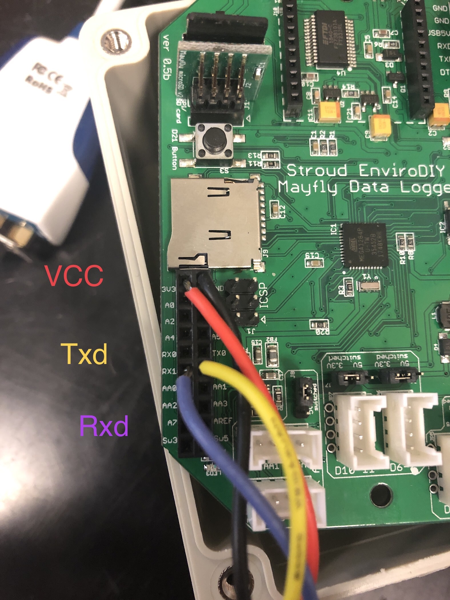
Thanks for the reply and pointers! I bought an adapter, but I’m unsure if I’m hooking it up correctly. Would you mind looking at the attached pictures for reference? I’m unsure of how the converter takes in serial data and sends it to the Mayfly…
Attachments:
-
2019-10-04 at 5:48 PM #13208
That looks like the converter I have. If you’re sure you have the right A & B wires, your doppler is powered, and the lights on the adapter are flashing, but you’re still not getting anything on the Mayfly, try flipping the Tx and Rx wires. Different people have different opinions on whether Tx means “the pin I’m sending out data on” or it means “the pin to connect the other guy’s outgoing data pin”.
The A & B from your ADCP are red and black? That’s not a problem; I’m just surprised. Often red and black are used for power and ground, but each manufacturer does their own thing, so you have to check that in your manual. Also, if your manual labels those wire as “to” and “from” it’s not using RS485. You should be using wires labeled A and B (or sometimes Y/Z or D+/D-.)
RS485 communication requires two wires for communication in each direction, which is why they’re usually labeled A & B and not Tx and Rx. The high and low “bits” in RS485 are counted by checking the difference in voltage between the two wires. This means an RS485 signal can make it through longer wires, but it also means that communication usually only goes in one direction at a time. TTL on the other hand reads high and low “bits” on a single wire by checking the difference between the voltage on that wire and system ground. There are often two wires used, one wire for incoming data and one wire for outgoing data, so you can be talking and listening at exactly the same time (aka full duplex). To get full duplex in RS485 you need 4 wires. The adapter translates between the RS485’s two wires and the TTL wires, with some magic circuity to get the direction right (and also some fuses and other magic to make it all less likely to blow up).
While you’re still testing out your communication, program your Mayfly with a really simple sketch that will echo everything it hears from Serial1 to Serial so you can see it on the serial port monitor:
C++12345678910111213#include <Arduino.h>setup() {Serial.begin(115200);Serial1.begin(9600);Serial.println("Passing through data from Serial1");}loop() {while(Serial1.available()) {Serial.print(Serial1.read());}} -
2019-10-08 at 11:31 AM #13214
Thanks for the help!
I ran into another problem as I think something happened and I blew a chip in the ADCP… I’m trying to determine if voltages were different. The RS232 and 485 chips in the ADCPs are 3.3V and I thought I had everything hooked up correctly to the right voltages, but I’m wondering if the Tx and Rx on the board are 5V output, or the TTL converter somehow pushes out 5V (the documentation on the converter is confusing).
Sorry for the confusion on the red, black and white wires, they were just leaders attached to the end of the cable I had – red=blue and black=orange and white=green.
-
-
AuthorPosts
- You must be logged in to reply to this topic.