
Home › Forums › Infrastructure and Equipment › Powering Ideas
Tagged: +12V boost, Powering, Switchers
- This topic has 0 replies, 1 voice, and was last updated 2018-04-04 at 12:43 AM by
 neilh20.
-
AuthorPosts
-
-
2018-04-04 at 12:43 AM #12213
I’ve been working on a relatively low cost powering concept for some time, and got the basics working – so I would like to share it.
It is at the circuit level – so I apologize, its really for anybody tinkering at the circuit level.
I’ve added it as a PDF – so hope that works.My objective is to be able to use the low cost of LiIon battery packs as power storage, with a solar cell power capable of using a 15W solar panel to be able to charge them. So 15W is 3A@5Vs – so choosing for instance two 10Ahr LiIon battery packs the could be charged with a good 7hrs of solar power.
And a switchable +12V powering source for RS485sensors.
The core is to use LiIon battery packs – they are very pluggable, and the size can be calibrated to the project constraints – mechanical and powering.
I’m using two, as real life field experience has shown how sometimes even solar is limited for some periods at some locations, and it would be nice to be able to bring a fully charged battery to the site.
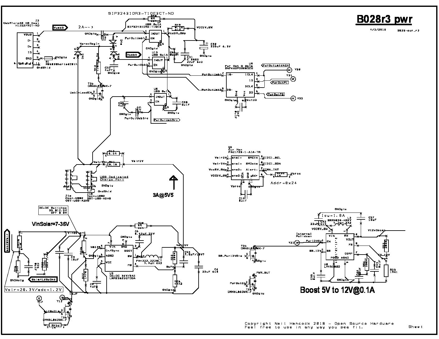
The nuts and bolts are that Solar Panels have an open circuit voltage – and the switcher IC LMR23625 can cope with 36V.
The +5V5/3A that can be supplied it is available either to charge two external LiIon battery packs or the powered system – which I’ve given a very generic name of “VCC5V_SW”
The two LiIon battery packs are charged by a dual low cost USB A connector.
The two LiIon battery pack deliver their power to the circuit via a microUSB.
The core of the power selector is a small USB 5V power switch SIP32431DR3
The sources for the “VCC5_SW” can be either VusbB or VusbA (not shown) or the solar 5V5.
The USB power switches SIP32431DR3 are buffered via a dual latch SN74AUP2G80DCU as don’t want any glitches in the power control.
It also has capability for power monitoring, using a low cost current monitor PAC1720-1-AIA, for measuring solar current, and current used by the circuit.
It also uses switchable +12V/100mA boost circuit LM4510SD. It takes power from the VCC_5VSW. When turned off, it disconnects completely from the VCC5V_SW
It also uses a processor to manage that power, and the low power processor has special power routing through a triple diode D4. The processor could be any low power processor, I’ve chosen a Cortex-M0 KL27Z, and I could explain some other time. Its very similar to pjrc.com/teensy/ Teensy LC KL25Z.I have tested the core of the power steering – but not the PAC1720.
So just some thoughts, and I’d be interested to hear any other power circuits.Attachments:
-
-
AuthorPosts
- You must be logged in to reply to this topic.