
Home › Forums › Mayfly Data Logger › Powering an Adafruit FONA
Tagged: FONA
- This topic has 3 replies, 3 voices, and was last updated 2017-06-15 at 2:28 AM by
ChanCafun.
-
AuthorPosts
-
-
2017-05-31 at 4:41 PM #2244
Greetings,
I recently received two Mayfly v0.5 units which I am evaluating. I used to use the Seeeduino Stalker v3.0 for projects, but I find the v3.1 they have replaced it with, among other problems, will not put out enough power to run an Adafruit FONA 808. Fixing this requires desoldering a surface-mount diode and shorting the pads, which is a little much to ask of most of the audiences I am working with.
Unfortunately, I am finding the same problem with the Mayfly. The switched outputs will not supply enough current for the FONA to power on at all, and when using the main 3.3v pin on either USB or LiPo power, the FONA turns on briefly but quickly performs an UNDER-VOLTAGE POWER DOWN.
That said, I see from the forums that some people are using the FONA with the Mayfly. What am I missing? Many thanks for any advice.
-
2017-05-31 at 11:51 PM #2245
The SIM808 module on the FONA must be powered directly from a 3.7v LiPo battery because it draws around 500mA during data operation, and can have occasional draw of up to 2 amps during a TX burst. The SIM808 module also requires a power source of 4.0v nominal, with a minimum of 3.4v and a max of 4.4v. So powering it directly from a 3.7v Lipo is the only reasonable option.
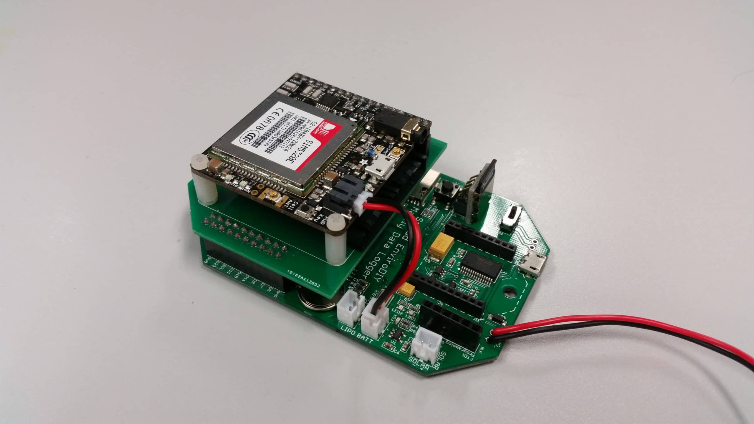
This is the reason there are two JST “LiPo Batt” jacks on the Mayfly. If you want to use a FONA with a Mayfly, you’ll need to connect a LiPo battery directly to one of the JST jacks labeled “LiPo” on the Mayfy. Then use a JST jumper to connect the JST jack on the FONA’s to the Mayfly’s other “LiPo” jack.
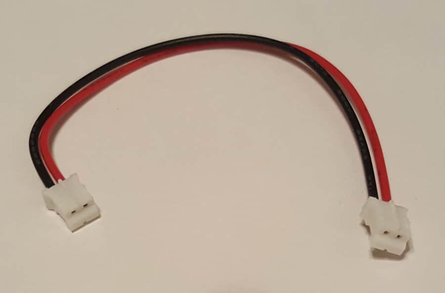
I’ve attached a picture of a JST jumper. We use GPRSbee cellular modules with almost all of our deployments and they come with one of these jumpers. You can make you own jumper by splicing together 2 standard JST pigtail cables.
Be sure to connect the “Vio” pin on the FONA to the 3.3v rail of the Mayfly in order to properly configure the logic level shifting of the FONA’s circuitry.
If you’re looking for the easiest 2G option, I highly recommend the GPRSbee (https://shop.sodaq.com/en/gprsbee.html). It plugs directly into the Bee socket on the Mayfly. Just add the JST power jumper and the u.fl antenna (included) and it’s ready to go. I’ve been using dozens of them for several years now and I really like them.
Attachments:
-
2017-06-01 at 10:14 AM #2249
That’s very helpful, thanks. In the past I had good results with custom shields that connected the FONA’s Batt pin to the Stalker’s VCC pin, but the new design uses a diode that cannot handle the current necessary.
-
2017-06-15 at 2:28 AM #2259
-
-
AuthorPosts
- You must be logged in to reply to this topic.