
Home › Forums › Environmental Sensors › PH Sensor Issue
- This topic has 10 replies, 2 voices, and was last updated 2019-07-19 at 11:33 AM by
Gera.
-
AuthorPosts
-
-
2019-07-18 at 10:47 AM #12970
Hello everybody, I am currently trying to work with the Mayfly board to find pH. I have the pH Electrode E201 – BNC and the board that comes with it is the DIY PH-4502C. I am having a problem when trying to calibrate this thing with the mayfly board. the 5v voltage pins of this board do not work as the arduino does. When I calibrate it with the arduino UNO it gets at the 2.5V that it is needed, with the mayfly it stays at 3.73V and I am trying to use resistors to see if that can help me reduce the voltage and it does not work either. I try using 3.3V and it still stays at 3.73V when calibrating. I need to use the mayfly board for the project that I am doing. Can somebody help me out please?
-
2019-07-18 at 3:45 PM #12971
Which analog pins of the Mayfly are you attempting to use to measure the voltage? And can you share the code you’re using to read the voltage?
-
2019-07-18 at 3:50 PM #12972
pin A0,
here is the code:
void setup() {
// initialize serial communication at 9600 bits per second:
Serial.begin(9600);
}// the loop routine runs over and over showing the voltage on A0
void loop() {
// read the input on analog pin 0:
int sensorValue = analogRead(A0);
// Convert the analog reading (which goes from 0 – 1023) to a voltage (0 – 5V):
float voltage = sensorValue * (5.0 / 1023.0);
// print out the value you read:
Serial.println(voltage);
delay(300);
} -
2019-07-18 at 4:01 PM #12973
What pin is the sensor getting power from? If it’s the Switched 5v pin (labeled SW5), or from one of the grove terminals (assuming you’ve moved the jumper over to the 5v setting), you still need to switch on the 5V boost regulator by putting this line, preferably in your setup routine:
digitalWrite(22, HIGH);
The 5v boost regulator (as well as the switched 3.3v aux regulator) are not enabled unless you set pin 22 high. This is so the regulators don’t stay on all the time and waste power when the logger is sleeping between measurements. If you want to leave it on constantly, it’s easiest to put the statement above in your setup routine. If you’re making a sleeping logger, then you’ll want to set 22 high and low at different times in your loop, making sure to add sufficient time for the sensor to settle after powering up before taking a reading.
-
2019-07-18 at 4:09 PM #12974
The pin is USB5V, I tried using that SW5 as well. I tried using all those slots, all of them gave me the exact same value of 3.73V.
-
2019-07-18 at 4:14 PM #12975
You mean the USB5V on the FTDI header? That’s only used if you’re supplying power to the board via an FTDI adapter when programming. You should definitely be using the SW5 pin for powering a sensor and not using the FTDI header.
What does your resistor divider network look like? What values, and how do you have them connected in relation to the sensor, and the power and ground pins of the Mayfly? Is the sensor properly connected to a Ground pin on the Mayfly as well?
-
2019-07-18 at 4:20 PM #12976
Also, you need to use 3.3 volts as the board voltage in your conversion formula and not 5.0 volts. And if you’re measuring a 50/50 voltage divider, you’ll then need to double the measured voltage to get the true sensor voltage. So:
float voltage = (sensorValue * (3.3 / 1023.0)) * 2.0;
-
2019-07-18 at 10:32 PM #12977
Sorry for the late answer I had some stuff to do.
Okay so, the circuit is connected like this:Voltage: V+ which is the 5V DC connected to SW5
Ground: Ground to Ground
Analog = PO or PH analog output is connected to the Analog pin A0
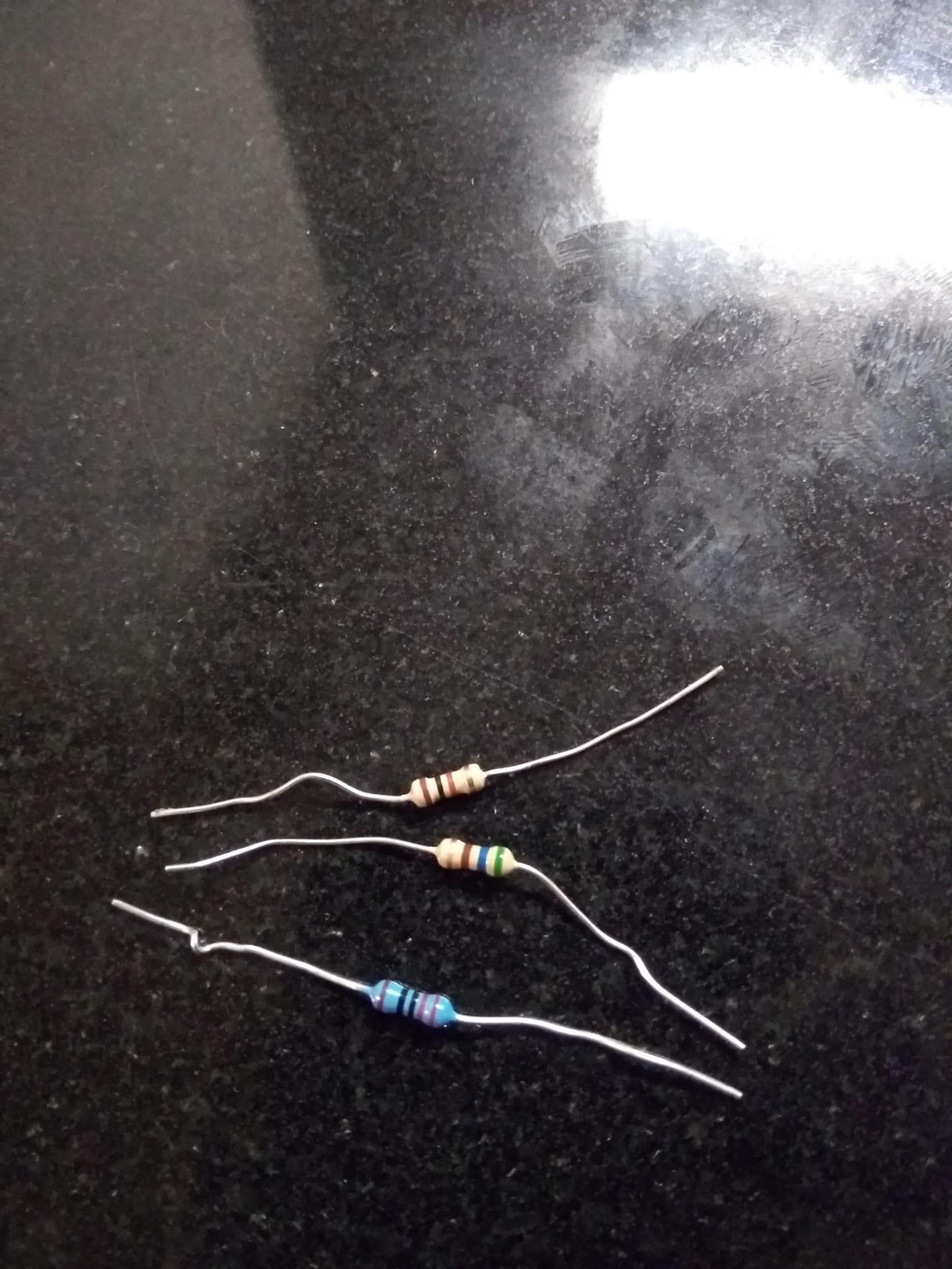
I used three resistors to test which one will be close to the voltage required, I will post a picture of the three of them.
The voltage output I get from your code displays more than 5V, I can’t calibrate it to 2.5V that way.
The circuit is guarantee is properly connected.Also you have been helping me out a lot, I appreciate it.
Attachments:
-
2019-07-18 at 10:56 PM #12979
Also, with the code you provided, if I do not use the voltage divider I can calibrate it to 2.5V if I remove the *2 from the equation. I am first time coder and also the mayfly is something new for me as well, I am learning little by little how this thing works. So the calibration will be right if I use the code without multiplying the 2?
-
2019-07-19 at 10:07 AM #12980
The way a voltage divider works is for you to use 2 resistors in series, and then you measure the junction between the two resistors, and you’ll see a fraction of the overall voltage. The best method for breaking a 5v signal down to something the Mayfly can tolerate would be to use two identical value resistors (like 10k-ohms each), so that way the point your measuring is exactly half of the overall voltage, hence the *2 multiplication in my formula above. You can use any ratio you want, but a pair of identical resistors is easiest for your first voltage divider.
-
2019-07-19 at 11:33 AM #12981
Alright. I am getting the data right. Thank you for your help.
-
-
AuthorPosts
- You must be logged in to reply to this topic.