
Home › Forums › Mayfly Data Logger › Modify SW5V boost to 12V
- This topic has 11 replies, 5 voices, and was last updated 2018-04-03 at 1:08 AM by
 neilh20.
-
AuthorPosts
-
-
2017-10-15 at 10:16 PM #2366
Dear admin,
I am working on reading the In-situ LevelTroll 400 water level sensor through Mosbus, it required a 12V-24V input.
I have check the Mayfly sw5V boost SC4503 datasheet, it allow step up voltage up to 27V.
If I follow the output voltage formula in the datasheet R1 = R2 (Vout/1.25V – 1), If Vout = 12V, R1/R2 = 8.6
I need to modify the mayfly on board resistor R19 from 10k to 3.3k which give me output voltage around 12.65V.I want to confirm is it okay to do it without modify other components in the sw5V boost circuit??
Your help is much appreciated
Best regards
Calvinbtw, below is my successful 3G datalogger design using Mayfly 🙂
Attachments:
-
2017-10-18 at 12:14 PM #2370
What version of the Mayfly board do you have? The newer boards have a different regulator than earlier versions, so make sure you’re looking at the right datasheet and resistors.
If you’re comfortable removing and reinstalling SMT resistors, then it is possible to remove that resistor and replace it with another one to achieve different output voltages. But you have to be careful with supplying 12v to external devices so that you don’t exceed the maximum safe current and that the return data is at a safe voltage, otherwise you’ll damage the Mayfly. It’s likely you might need some external level shifters on the return data lines, which is why I didn’t include 9v and 12v excitation options on the Mayfly to begin with. Things can quickly go bad if users aren’t careful about voltage levels, so I decided to keep higher voltage stuff off the Mayfly. You can add an external boost regulator for just a few dollars each (5, 9 or 12v) from here: https://www.pololu.com/product/2117
Then you can put that boost regulator on a Grove protoshield (https://www.robotmesh.com/grove-protoshield) along with a level-shift breakout and then a header or screw terminal, and then you’ll have everything you need for safely powering an external device with a different voltage.
-
2017-12-20 at 1:52 PM #2464
Hi Calvin
Nice to see the pic of the 3G logger.
I was wondering if you got the link to the LT400 working.
I’ve been attempting to access the LT500 but not had any success decoding the LT500 protocol that runs on top of the modbus/RS485.
I have had packets as per the “Insitu Modbus_Communication_Protocol_5.10.pdf” but seems there is some initialization sequence that is needed before reading the sensors. I wonder how far you got with it.
I have got Keller Nano Level device that is very accurate in low water (capactive sensors) and water temperature change polling.
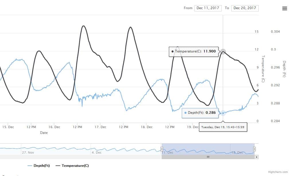
My hardware arrangement is prototype with a RS485 plugin using an Olimex STM32-H407 running off a 12V source. Pic enclosed. This is of the sensor in stable jar of water so the water depth isn’t varying except for evaporation. The sensor depth reading variation is from temperature variation.BTW – I would think that with the mayfly interfacing to an RS485 chip (sparkfun has them) – the 12V would be well isolated. But as Shannon said, the 12V will fry 3V mayfly logic should they ever meet.
One of the issues with any electronics is they often take a surge on power up. For 12V sensors this may be a problem with a boost circuit, switched the way it is on the Mayfly. Powering is always tradeoffs and it may take some characterization. https://github.com/EnviroDIY/EnviroDIY_Mayfly_Logger/issues/1Attachments:
-
2017-12-28 at 1:47 AM #2470
Hi Neilh,
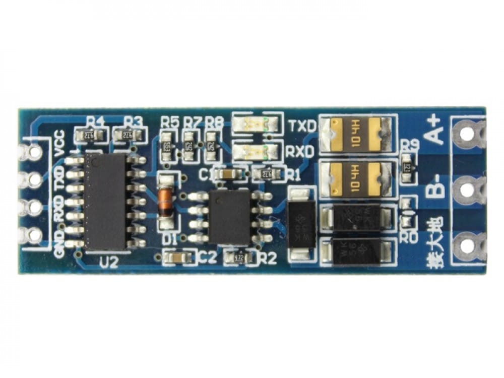
I had successfully read LT400 through Modbus potocol. The TTL to RS485 coverter I was use showed in the attached photo.
I am using an external 12V battery for the testing setup.
I burnt out one of the logic pin somehow, I could not find out the reason. maybe the 12V meet the logic pin accidentally.
I sent a private message to you with the link to download my LT400 Modbus test programme, hope that it can help you.
My 3G datalogger read LT400 through SDI12. I directly connect 3.7 Li battery to the LT400 power. It worked very well so far.
I remember I tried once connect 3.7 Li battery to LT400 and read it through Modbus. It worked, but I am not testing it hardly so I am not sure of it.
So far my SDI12 datalogger working well and I am not putting time modify it to Modbus.(I am now trying to read Soil Instrument TLT6 MEMS tilt sensor by Mayfly datalogger)
Attachments:
-
2017-12-31 at 4:36 PM #2472
Thanks for the link – I think I hadn’t figure out the right registers addresses to read, so very useful.
I’m assuming your include <ModbusMaster.h> pulls https://github.com/4-20ma/ModbusMasterThe direction I’m heading in is with the BeagleBone Green Wireless and generating Modbus 12V off 5V. Will post more when I have it tested.
-
2018-01-11 at 10:42 AM #2476
I’m sorry I’ve missed this thread until now.
I agree that when interfacing with a 12V powered device through the RS485 adapter, there shouldn’t be much risk of frying the Mayfly. I would still go with a separate power boost instead of stripping the resistors on the Mayfly, though.
I would *NOT* recommend any RS485-to-TTL adapters based on the MAX485/MAX3485 chip. Getting the timing right for the enables is *really* tricky and I haven’t been able to get it to work successfully at all. I have bought a couple of boards with automatic flow control (looking similar to the one Calvin pictured) and all of them have worked.
WRT Modbus communication, I have not tried to interface with In-situ probes yet, but in working with other sensors I found the ModbusMaster library to be really confusing. I ended up writing my own library to handle modbus interfacing with sensors. It’s specifically written with someone who knows very little about modbus in mind. That library is on GitHub if you’re interested: https://github.com/EnviroDIY/SensorModbusMaster
-
2018-01-11 at 12:54 PM #2477
Hi Sara.
Nice to hear someone else using Modbus/RS485. Thanks for sharing the library.
The realtime serial processing is a challange and I have got it working on different systems. The first sign to look for is whether its supported in chips UART through DTR.
One issue with the automatic flow control is that it uses a couple of mA to maintain the line state.
I hope to share more as a I get some results.
Neil -
2018-02-01 at 2:09 PM #2484
Sara has done some great coding work with her SensorModbusMaster library, primarily in support our use of the high quality and inexpensive sensors from YosemiTech. We’ve developed a specific library for all YosemiTech sensors, which makes accessing all of the power functions quite easy: https://github.com/EnviroDIY/YosemitechModbus. All of this works with our powerful EnviroDIY ModularSensors library.
I’ll be working this month on connecting a Keller Acculevel+ Submersible Pressure sensor, building off of the SensorModbusMaster library.
We’ll keep you updated.
-
2018-02-01 at 5:49 PM #2485
Hi Anthony, great to see the SensorModbusMaster detail.
FYI for the Keller Acculevel I found they had the CRC16 bytes switched around. Its well documented in the manual “Keller CRC16.
Also, if you are looking for accurate measurement at low levels of stream depth with low temperature dependency I’ve found the Keller Nanolevel to be about +/-0.05% across TEB. It uses a capactive sensor rather than the piezo resistive sensor of the acculelvel series. However it only has a range of 0-11′, and wider sensor body.
When considering the accuracy of the Acculevel, in discussion with Keller, I found their base level accuracy TEB (Total Error Band) is for +/-30′ Full Scale – so specifying a sensor with a range of less than that, the TEB is still for +/-30′. Not so much of a problem if the water temperature is constant in deeper water, but becomes relevant for measuring low water levels were there can be significant temperature shifts over a day.The Keller devices allow for a number of types of jackets – “Polyethelene for general purpose” ie water is now recommended. The early Acculevel datasheets and Instrumart techsupport recommended Hytrel jacket and these developed fissures after only 6months in the water, and had to be replaced – a lot of field work.
-
2018-02-03 at 7:18 PM #2487
Hello @aufdenkampe
I was just wondering, for the Modbus/Keller Acculevel, for field deployment what you are doing for powering/mechanical and pushing to your intranet. Perhaps this is a topic by itself, be interested to discuss as I’m developing some circuits for same 🙂 -
2018-04-02 at 1:12 PM #12211
@neilh, thanks for all of these tips. I’m just now diving back into all this, and actually need to make a lot of progress in the next 10 days.
I decided to still go with the Acculevel, because I needed the extra depth range.
Do you have any working Arduino code for the Acculevel? or even the nanolever. It would be a great place to start. My goal is to build a KellerModbus library, that builds on our EnviroDIY/SensorModbusMaster library.
For powering, we just developed a shield for the Mayfly and will be posting those plans & Eagle files and soldering instructions to the EnviroDIY/SensorModbusMaster library.
For sending to the internet, we’re using our EnviroDIY/ModularSensors library to post to the new EnviroDIY Water Quality Data Portal.
-
2018-04-03 at 1:08 AM #12212
Hello @aufdenkampe,
Great to hear you are doing a power shield with capability to deliver to the EnviroDIY water quality data portal.
There hasn’t been a hw solution yet that I liked, that so I haven’t done anything with the Arduino libs. Maybe that will change.:)
I’m planning on doing a poster at http://calsalmon.org/conferences/36th-annual-salmonid-restoration-conference on different types of pressure sensors for “measuring low water levels accurately across a 10C diurnal change in temperature.”
If you have a solution (or a plan) to have a switchable +12V from a low cost solar powered storage source I’d be happy to reference it.
My objective is switchable +12V powered sensors, with low cost power storage, charging from ~15W solar panel, with a comms solution that can deliver the reading to an internet location and be accessed over the internet.
The assumption is that sensor depth readings are taken every 15minutes, and cellular data is pushed ~ 1-4Hrs.
The system shuts down inbetween activity and takes less than 0.5mA.
The power storage design assumes little sunlight for storms that are two weeks at a time in parts of the year.
Dynamic power issues are of course Cellphones(2G/3G) can take ~0.7A for about a 1Minute to connect and deliver to an internet location.I did a software prototype on Nuttx(PX4)/Olimex H407, but gave up when I scoped the amount of work still needed to support some of the basic Nuttx subsystems.
It has been running for over a year on the H407 board with external +12V, reading a Keller Nanolevel over RS485 and pushing to Thingspeak/ParticileWiFi
I haven’t attempted to standardize on the modbus lib – so its probably not very useful.
See modbusm_poll_device()
https://bitbucket.org/neilh20/nuttapps/src/e4d5088e591b0f126fc0e8b6b3662f6ffd3cbfcf/examples/modbus/master1/modbusm_user.c?at=dvlp_ensy1&fileviewer=file-view-default
The results are visible through http://azonde.info/pm2/WaterDepthTempNanoLevel.htm that pulls from thingspeak.
-
-
AuthorPosts

- You must be logged in to reply to this topic.