
Home › Forums › Infrastructure and Equipment › DIY auto sampler
- This topic has 8 replies, 3 voices, and was last updated 2022-03-31 at 6:23 PM by
 neilh20.
-
AuthorPosts
-
-
2022-03-23 at 4:12 PM #16859
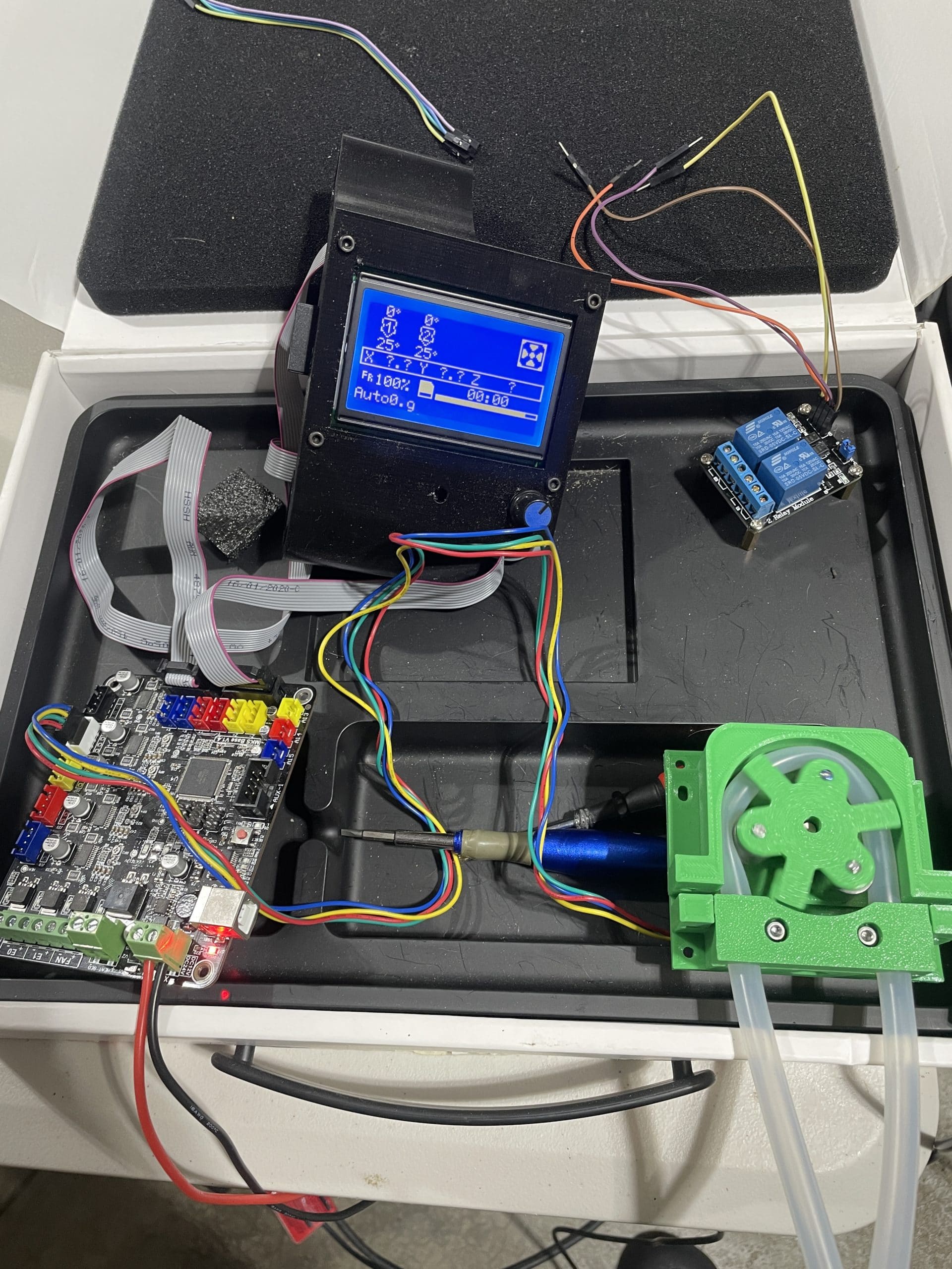
During my lunch break today I managed to slap together a prototype auto sampler that could potentially complement the mayfly. It’s also pretty cheap. I borrowed a 3d printed peristaltic pump design that I have borrowed before for an automated sediment toxicity renewal system that I have built for our lab. It has been very reliable and I already know how to get it run automatically using Marlin firmware. This is basically a 3d printer or cnc machine build but only utilizing one motor. It will run from a separate power source and is connected to the mayfly via a single or dual relay board.
hardware
Here I am using an old 3d printer board that was around $30 brand new. This board does not have an on board SD card, so I am using a LCD board for the interface. A board with an on board SD card could run headless. An SD card adapter could also be an option. Most of the pump is printed but there are 505 bearings and some m3 nuts and bolts. I’m using a 17 nema stepper motor, which is a basic 3d printer motor. I usually us a high torque one, but this one is an extra from another build. I’m going to stuff it in a harbor freight weather proof box, which is basically a knock off of pelican. Wiring instructions are easy, plug the motor into the E0 motor. Thought other motors could be added to say operate a bottle carousel.
Firmware
Marlin is the open source firmware that gets flashed to the board. It can be modified in platformio pretty easily. There is a custom user menu that can have machine specific custom command added to the menu. This board only has room for 5, though some can have up to 25 custom commands. Marlin also does this cool thing where is will run a program automatically. All you have to do is name it auto0.g and once the unit is turned on it will run that code. All the mayfly will have to do is turn on the relay for a period of time, allowing the sampler to run its gcode and then turn off the relay.
Gcode
It’s pretty simple. I hand right the codes for the renewal machines and this is a part of that code. It basically selects the motor, puts the motor in relative mode, runs the pump slow, then fast one direction, Beeps (m300), runs in reverse to clear out the sampling hose and deactivates the motor. The number following the E refers to the number of steps the motor will take. one can calibrate the pump using these steps.
12345678910111213141516T0M83G1 E10 F400G1 E200 F1400G4 S4M300 S440 P200M300 S660 P250M300 S880 P300G1 E-15 F400G1 E-300 F1400G4 S2M84I have a new relay coming with the grove plugs. I had bread boarded out the one I had but thought the grove would be a cleaner look since it’s there. it will also allow for the 5v to control the relay, I believe.
It’s a pretty quick way to get a sampler like this. One could easily make use of the other motors to increase sampling capacity in a couple of ways. The turn table idea mention earlier is one way. adding a second pump set all together with a dual relay would get you two sample that could be trigger under different conditions. A cnc like build in the top of a cooler could allow the hose to move from container to container.
Attachments:
-
2022-03-23 at 5:55 PM #16870
The pump project that I used can be found here: https://www.thingiverse.com/thing:3148717
Marlin: https://marlinfw.org/
Here is how I currently put this strategy into action. A wifi connected outlet turns the machine on and off.
-
2022-03-25 at 9:23 AM #16876
@craig607, thank you for posting this! Would you consider expanding on it as a guest blogger here on EnviroDIY?
-
2022-03-31 at 11:14 AM #16886
-
2022-03-31 at 12:17 PM #16887
@craig607 fascinating, thankyou for the brainstorm.
Looking at the stepper motor power draw, seems like managing where that power draw comes from would be part of the design. For one source of steppers that give a range of V and A, there is a lot of choice https://www.adafruit.com/?q=stepper&sort=BestMatch
Happy to brainstorm that part if its useful. -
2022-03-31 at 3:38 PM #16888
@neilh20 For my sediment machines I use a high torque 920z Nema 17 motor and is rated for 3.36v and 2.1amps. It works very reliably. The one I prototyped is a 76oz Nema 17 which is rated for 4.2v and 1.5amps. I have a pancake motor as well but they are lower torque. Here is a reference to a number of steppers from the 3d printing side of things: here
Generally the biggest issue is to balance the torque of the motor, the fit of the printed pump head, and the feed rate for which you move the motor. In that gcode I provided above, there is two steps to the sampling stage. The pump first moves (G1 E10 F400) tens step at a feed rate of 400. Then is moves faster, (G1 E200 F1400) moving. When reversing the pump it does this same two stage process. I found that it helps reliability and believe it takes full advantage of the torque the motor provides. I could be missing something but this is what I have experienced with this particular pump design.
-
2022-03-31 at 4:26 PM #16889
@craig607 great to see the stepper functionality and managing it with the GCODEs though I wasn’t clear what the Marlin board is, and how it gets activated. Is the relay the power switch ON, or a pull to ground input.
This probably says how basic my view is, looking at powering, the 4.2V is nice as it maps to a LiPo battery, though LiPo are 4.2V decreasing to 3.8V. With 1.5As power draw the battery needs to be sized for the length of time the pumps can operate.
I’m imagining a use case of it being solar powered, so guessing at a separate LiIon battery pack, with probably separate charger and possibly solar panel – possibly all in the Marlin board? Just checking. Also, thinking typically need to measure the LiIon voltage to check its being charged. -
2022-03-31 at 4:57 PM #16890
@neilh20 so the board here is called a MKS Base V1.4 if i remember correctly. It’s an old 3d printer board. There are a slough of options and which is used really doesn’t matter. They are all, like the mayfly, a modified arduino. Though these use the arduino mega as their main design.
I have the relay controlling the power to the board itself. The power source is still TBD. These board generally take in 12v or 24v. A separate charge controller and 12v battery could make quick work of this task. Though if there are regular maintenance visits, then there is potential to just swap out batteries. The battery basically just needs to sit idle, until sampling, in which case someone should be on the way to pick it up. battery swaps can occur then too. Just off the top of my head I’m thinking maybe a 12v 5ah battery, or the very easy to get 12v 7ah battery. Another option might be tool batteries with and adaptor. This would make swapping things out very quick and wont allow for it to be hooked up incorrectly. Something like this.
This is a lot of spit balling.
-
2022-03-31 at 6:23 PM #16891
@craig607 yes totally agree, spit balling or back of the envelope sketch 🙂
So great – you can see I’m asking the dumb questions, and if some one has to pick up the bottles every so-often, then can also switch out the power source batterys :).I see now how the hardware fits in, and found the schematics https://github.com/makerbase-mks/MKS-GEN/tree/master/hardware
Interesting, look forward to it 🙂
-
-
AuthorPosts
- You must be logged in to reply to this topic.