
Home › Forums › Mayfly Data Logger › Analog-to- Digital Converter Port on Mayfly Data Logger
- This topic has 5 replies, 3 voices, and was last updated 2019-10-10 at 4:15 PM by
Rachana.
-
AuthorPosts
-
-
2019-09-26 at 8:04 PM #13174
Hello @shicks,
I am trying to connect the OBS 3+ of Campbell Scientific(turbidity sensor) to the Mayfly Data Logger using the ‘Auxiliary 16-bit, 4-channel Analog-to-Digital Converter’ port.
Mayfly board has been powered up by connecting it to a PC via USB. It receives 5V external input when connected to ‘LiPo battery connector’ port. But when trying to power up the turbidity sensor by connecting to the ‘Auxiliary 16-bit, 4-channel Analog-to-Digital Converter’ port, there is 0V at that port. Any help with information about how to connect the sensor to the Mayfly board is highly appreciated.
Thank you.
-
2019-09-27 at 7:37 AM #13175
Are you referring to the two Grove ports in the lower left corner of the Mayfly? All of the Grove ports (and the Sw3 and Sw5 pins in the headers) are designed to only be powered when you set pin D22 high. This is so that you can turn any external sensors on or off independently from other things on the Mayfly. Setting D22 high turns on the external 3v and 5v regulators, and anytime they are on you’ll see a red LED in the corner of the board light up (LED3).
Also be aware that the maximum incoming voltage that the ADS1115 can read is 3.3v, as determined by the Vcc of the Mayfly. You can buy the OBS3+ in different voltage output options, so if you bought the one with 5v output at full scale, you’ll need to use a voltage divider to protect the Mayfly from seeing anything greater than 3.3v. We always buy the OBS3+ with the 2.5v output option so that the max voltage will never exceed Vcc. And if you do use a voltage divider, make sure to account for that in the formula you use for the ADS1115 to convert bits to volts which and translate into sensor output to match up with the sensor calibration equations provided with each sensor.
-
2019-09-27 at 12:58 PM #13176
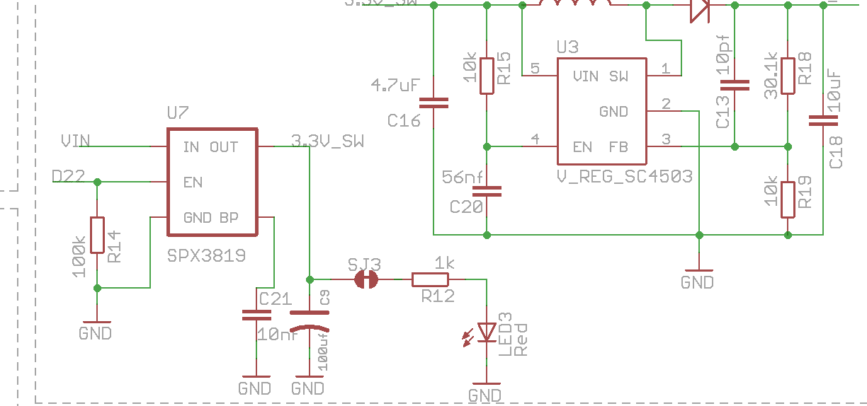
Thank you for the information. But I am unable find the D22 pin on the board. I am using ver 0.5b. I checked the schematic and tried locating the TOSC1/D22 but could not. Could find all the resistors and capacitors in the 3.3V switched and 5V boost circuit except the D22 enable pin. Also, how to set the pin high if located? Thank you.
Attachments:
-
-
2019-09-27 at 4:32 PM #13181
You set pin 22 high in whatever program/sketch you’re using.
-
2019-09-27 at 4:39 PM #13182
Mayfly D22 is not a physical pin on the board, it’s processor pin 22, which means you set it high or low using digitalWrite commands in your sketch, just like you would with pin 8 or 9 to turn the red or green LEDs on or off. If you’re new to Arduino or the Mayfly, you might try working through example sketches or workshop sketches in our Github repo to familiarize yourself with the operation before you connect an expensive sensor like an OBS3 to a Mayfly.
-
2019-10-10 at 4:15 PM #13222
Thanks for the guidance. I went through the examples in the git repo and found the following piece of code (abridged for Campbell OBS3+ turbidity sensor). I have a couple of questions. Could you please help me with them?
1. The OBS3+ I am using operates at 5V and it needs D22 pin. Pin D22 is enabled in the code. But how to mention in the code that it is switched to 5V? Below are the code lines where I could get a reference for D22 and greater than 3.3V(5V in this case)
float getBatteryVoltage()
{
if (mcuBoard.sensorValues[0] == -9999) mcuBoard.update();
return mcuBoard.sensorValues[0];
}const int8_t sensorPowerPin = 22
// Create the log file, adding the default header to it
// Do this last so we have the best chance of getting the time correct and
// all sensor names correct
// Writing to the SD card can be power intensive, so if we’re skipping
// the sensor setup we’ll skip this too.
if (getBatteryVoltage() > 3.4)
{
dataLogger.turnOnSDcard(true); // true = wait for card to settle after power up
dataLogger.createLogFile(true); // true = write a new header
dataLogger.turnOffSDcard(true); // true = wait for internal housekeeping after write
}2. As the voltage is more than 3V- a voltage regulator is needed. Does the line below help? Does pin A6 work as a voltage divider?
const int8_t resistorDividerPin = A6; //Resistor divider on the battery input of Mayfly board3.I am trying to connect the sensor to the grove pins ‘Analog to Digital Convreter pins- AA0 and AA1’.
“const uint8_t ADSi2c_addr = 0x48; // The I2C address of the ADS1115 ADC” — is this statement in the code enough to get output from ports AA0 and AA1.4. The lines below say that a log file will be created.
“dataLogger.createLogFile(true); // true = write a new header” —>Does this mean I have to write another header in the code or does it print the sample values under a default header?
// Create the log file, adding the default header to it
// Do this last so we have the best chance of getting the time correct and
// all sensor names correct
// Writing to the SD card can be power intensive, so if we’re skipping
// the sensor setup we’ll skip this too.
if (getBatteryVoltage() > 3.4)
{
dataLogger.turnOnSDcard(true); // true = wait for card to settle after power up
dataLogger.createLogFile(true); // true = write a new header
dataLogger.turnOffSDcard(true); // true = wait for internal housekeeping after write
}Could you please guide on what additions and modifications are needed to the code?
/*****************************************************************************
obs3+.ino
Written By: Sara Damiano (sdamiano@stroudcenter.org)
Development Environment: PlatformIO
Hardware Platform: EnviroDIY Mayfly Arduino Datalogger
Software License: BSD-3.
Copyright (c) 2017, Stroud Water Research Center (SWRC)
and the EnviroDIY Development Team
This example sketch is written for ModularSensors library version 0.21.2
This sketch is an example of logging data to an SD card as should be used by
groups involved with The William Penn Foundation’s Delaware River Watershed
Initiative at sites without cellular service.
DISCLAIMER:
THIS CODE IS PROVIDED “AS IS” – NO WARRANTY IS GIVEN.
*****************************************************************************/// ==========================================================================
// Include the base required libraries
// ==========================================================================
#include <Arduino.h> // The base Arduino library
#include <EnableInterrupt.h> // for external and pin change interrupts// ==========================================================================
// Data Logger Settings
// ==========================================================================
// The library version this example was written for
const char *libraryVersion = “0.21.2”;
// The name of this file
const char *sketchName = “obs3+.ino”;
// Logger ID, also becomes the prefix for the name of the data file on SD card
const char *LoggerID = “XXXXX”;
// How frequently (in minutes) to log data
const uint8_t loggingInterval = 5;
// Your logger’s timezone.
const int8_t timeZone = -5; // Eastern Standard Time
// NOTE: Daylight savings time will not be applied! Please use standard time!// ==========================================================================
// Primary Arduino-Based Board and Processor
// ==========================================================================
#include <sensors/ProcessorStats.h>const long serialBaud = 115200; // Baud rate for the primary serial port for debugging
const int8_t greenLED = 8; // MCU pin for the green LED (-1 if not applicable)
const int8_t redLED = 9; // MCU pin for the red LED (-1 if not applicable)
const int8_t buttonPin = 21; // MCU pin for a button to use to enter debugging mode (-1 if not applicable)
const int8_t wakePin = A7; // MCU interrupt/alarm pin to wake from sleep
// Set the wake pin to -1 if you do not want the main processor to sleep.
// In a SAMD system where you are using the built-in rtc, set wakePin to 1
const int8_t sdCardPwrPin = -1; // MCU SD card power pin (-1 if not applicable)
const int8_t sdCardSSPin = 12; // MCU SD card chip select/slave select pin (must be given!)
const int8_t sensorPowerPin = 22; // MCU pin controlling main sensor power (-1 if not applicable)const int8_t resistorDividerPin = A6; //Resistor divider on the battery input of Mayfly board
// Create the main processor chip “sensor” – for general metadata
const char *mcuBoardVersion = “v0.5b”;
ProcessorStats mcuBoard(mcuBoardVersion);// ==========================================================================
// Maxim DS3231 RTC (Real Time Clock)
// ==========================================================================
#include <sensors/MaximDS3231.h>// Create a DS3231 sensor object
MaximDS3231 ds3231(1);// ==========================================================================
// CAMPBELL OBS 3 / OBS 3+ Analog Turbidity Sensor
// ==========================================================================
#include <sensors/CampbellOBS3.h>const int8_t OBS3Power = sensorPowerPin; // Pin to switch power on and off (-1 if unconnected)
const uint8_t OBS3numberReadings = 10;
const uint8_t ADSi2c_addr = 0x48; // The I2C address of the ADS1115 ADC
// Campbell OBS 3+ Low Range calibration in Volts
const int8_t OBSLowADSChannel = 0; // The ADS channel for the low range output
const float OBSLow_A = 0.000E+00; // The “A” value (X^2) from the low range calibration
const float OBSLow_B = 1.000E+00; // The “B” value (X) from the low range calibration
const float OBSLow_C = 0.000E+00; // The “C” value from the low range calibration// Create a Campbell OBS3+ LOW RANGE sensor object
CampbellOBS3 osb3low(OBS3Power, OBSLowADSChannel, OBSLow_A, OBSLow_B, OBSLow_C, ADSi2c_addr, OBS3numberReadings);// Campbell OBS 3+ High Range calibration in Volts
const int8_t OBSHighADSChannel = 1; // The ADS channel for the high range output
const float OBSHigh_A = 0.000E+00; // The “A” value (X^2) from the high range calibration
const float OBSHigh_B = 1.000E+00; // The “B” value (X) from the high range calibration
const float OBSHigh_C = 0.000E+00; // The “C” value from the high range calibration// Create a Campbell OBS3+ HIGH RANGE sensor object
CampbellOBS3 osb3high(OBS3Power, OBSHighADSChannel, OBSHigh_A, OBSHigh_B, OBSHigh_C, ADSi2c_addr, OBS3numberReadings);// ==========================================================================
// Creating the Variable Array[s] and Filling with Variable Objects
// ==========================================================================
#include <VariableArray.h>Variable *variableList[] = {
new CampbellOBS3_Turbidity(&osb3low, “12345678-abcd-1234-efgh-1234567890ab”, “TurbLow”),
new CampbellOBS3_Turbidity(&osb3high, “12345678-abcd-1234-efgh-1234567890ab”, “TurbHigh”),
new ProcessorStats_Batt(&mcuBoard, “12345678-abcd-1234-efgh-1234567890ab”),
new MaximDS3231_Temp(&ds3231, “12345678-abcd-1234-efgh-1234567890ab”)
};// Count up the number of pointers in the array
int variableCount = sizeof(variableList) / sizeof(variableList[0]);// Create the VariableArray object
VariableArray varArray(variableCount, variableList);// ==========================================================================
// The Logger Object[s]
// ==========================================================================
#include <LoggerBase.h>// Create a new logger instance
Logger dataLogger(LoggerID, loggingInterval, &varArray);// Device registration and sampling feature information
// This should be obtained after registration at http://data.envirodiy.org
// This is needed so the logger file will be “drag-and-drop” ready for manual
// upload to the portal.
const char *registrationToken = “12345678-abcd-1234-efgh-1234567890ab”; // Device registration token
const char *samplingFeature = “12345678-abcd-1234-efgh-1234567890ab”; // Sampling feature UUID// ==========================================================================
// Working Functions
// ==========================================================================// Flashes the LED’s on the primary board
void greenredflash(uint8_t numFlash = 4, uint8_t rate = 75)
{
for (uint8_t i = 0; i < numFlash; i++) {
digitalWrite(greenLED, HIGH);
digitalWrite(redLED, LOW);
delay(rate);
digitalWrite(greenLED, LOW);
digitalWrite(redLED, HIGH);
delay(rate);
}
digitalWrite(redLED, LOW);
}// Read’s the battery voltage
// NOTE: This will actually return the battery level from the previous update!
float getBatteryVoltage()
{
if (mcuBoard.sensorValues[0] == -9999) mcuBoard.update();
return mcuBoard.sensorValues[0];
}// ==========================================================================
// Main setup function
// ==========================================================================
void setup()
{
// Start the primary serial connection
Serial.begin(serialBaud);// Print a start-up note to the first serial port
Serial.print(F(“Now running “));
Serial.print(sketchName);
Serial.print(F(” on Logger “));
Serial.println(LoggerID);
Serial.println();Serial.print(F(“Using ModularSensors Library version “));
Serial.println(MODULAR_SENSORS_VERSION);if (String(MODULAR_SENSORS_VERSION) != String(libraryVersion))
Serial.println(F(
“WARNING: THIS EXAMPLE WAS WRITTEN FOR A DIFFERENT VERSION OF MODULAR SENSORS!!”));// Set up pins for the LED’s
pinMode(greenLED, OUTPUT);
digitalWrite(greenLED, LOW);
pinMode(redLED, OUTPUT);
digitalWrite(redLED, LOW);
// Blink the LEDs to show the board is on and starting up
greenredflash();// Set up some of the power pins so the board boots up with them off
// NOTE: This isn’t necessary at all. The logger begin() function
// should leave all power pins off when it finishes.
if (sensorPowerPin >= 0)
{
pinMode(sensorPowerPin, OUTPUT);
digitalWrite(sensorPowerPin, LOW);
}// Set the timezone and offsets
// Logging in the given time zone
Logger::setTimeZone(timeZone);
// Offset is the same as the time zone because the RTC is in UTC
Logger::setTZOffset(timeZone);// Attach information pins to the logger
dataLogger.setLoggerPins(wakePin, sdCardSSPin, sensorPowerPin, buttonPin, greenLED);
dataLogger.setSamplingFeatureUUID(samplingFeature);// Begin the logger
dataLogger.begin();// Set up the sensors, except at lowest battery level
if (getBatteryVoltage() > 3.4)
{
Serial.println(F(“Setting up sensors…”));
varArray.setupSensors();
}// Create the log file, adding the default header to it
// Do this last so we have the best chance of getting the time correct and
// all sensor names correct
// Writing to the SD card can be power intensive, so if we’re skipping
// the sensor setup we’ll skip this too.
if (getBatteryVoltage() > 3.4)
{
dataLogger.turnOnSDcard(true); // true = wait for card to settle after power up
dataLogger.createLogFile(true); // true = write a new header
dataLogger.turnOffSDcard(true); // true = wait for internal housekeeping after write
}// Call the processor sleep
Serial.println(F(“Putting processor to sleep”));
dataLogger.systemSleep();
}// ==========================================================================
// Main loop function
// ==========================================================================// Use this short loop for simple data logging and sending
void loop()
{
// Note: Please change these battery voltages to match your battery
// At very low battery, just go back to sleep
if (getBatteryVoltage() < 3.4)
{
dataLogger.systemSleep();
}
// If the battery is OK, log data
else dataLogger.logData();
}123456789101112131415161718192021222324252627282930313233343536373839404142434445464748495051525354555657585960616263646566676869707172737475767778798081828384858687888990919293949596979899100101102103104105106107108109110111112113114115116117118119120121122123124125126127128129130131132133134135136137138139140141142143144145146147148149150151152153154155156157158159160161162163164165166167168169170171172173174175176177178179180181182183184185186187188189190191192193194195196197198199200201202203204205206207208209210211212213214215216217218219220221222223224225226227228229230231232233234235236237238239240241242243244245246247248249250251252253254255256257258259/*****************************************************************************obs3+.inoWritten By: Sara Damiano (sdamiano@stroudcenter.org)Development Environment: PlatformIOHardware Platform: EnviroDIY Mayfly Arduino DataloggerSoftware License: BSD-3.Copyright (c) 2017, Stroud Water Research Center (SWRC)and the EnviroDIY Development TeamThis example sketch is written for ModularSensors library version 0.21.2This sketch is an example of logging data to an SD card as should be used bygroups involved with The William Penn Foundation's Delaware River WatershedInitiative at sites without cellular service.DISCLAIMER:THIS CODE IS PROVIDED "AS IS" - NO WARRANTY IS GIVEN.*****************************************************************************/// ==========================================================================// Include the base required libraries// ==========================================================================#include <Arduino.h> // The base Arduino library#include <EnableInterrupt.h> // for external and pin change interrupts// ==========================================================================// Data Logger Settings// ==========================================================================// The library version this example was written forconst char *libraryVersion = "0.21.2";// The name of this fileconst char *sketchName = "obs3+.ino";// Logger ID, also becomes the prefix for the name of the data file on SD cardconst char *LoggerID = "XXXXX";// How frequently (in minutes) to log dataconst uint8_t loggingInterval = 5;// Your logger's timezone.const int8_t timeZone = -5; // Eastern Standard Time// NOTE: Daylight savings time will not be applied! Please use standard time!// ==========================================================================// Primary Arduino-Based Board and Processor// ==========================================================================#include <sensors/ProcessorStats.h>const long serialBaud = 115200; // Baud rate for the primary serial port for debuggingconst int8_t greenLED = 8; // MCU pin for the green LED (-1 if not applicable)const int8_t redLED = 9; // MCU pin for the red LED (-1 if not applicable)const int8_t buttonPin = 21; // MCU pin for a button to use to enter debugging mode (-1 if not applicable)const int8_t wakePin = A7; // MCU interrupt/alarm pin to wake from sleep// Set the wake pin to -1 if you do not want the main processor to sleep.// In a SAMD system where you are using the built-in rtc, set wakePin to 1const int8_t sdCardPwrPin = -1; // MCU SD card power pin (-1 if not applicable)const int8_t sdCardSSPin = 12; // MCU SD card chip select/slave select pin (must be given!)const int8_t sensorPowerPin = 22; // MCU pin controlling main sensor power (-1 if not applicable)const int8_t resistorDividerPin = A6; //Resistor divider on the battery input of Mayfly board// Create the main processor chip "sensor" - for general metadataconst char *mcuBoardVersion = "v0.5b";ProcessorStats mcuBoard(mcuBoardVersion);// ==========================================================================// Maxim DS3231 RTC (Real Time Clock)// ==========================================================================#include <sensors/MaximDS3231.h>// Create a DS3231 sensor objectMaximDS3231 ds3231(1);// ==========================================================================// CAMPBELL OBS 3 / OBS 3+ Analog Turbidity Sensor// ==========================================================================#include <sensors/CampbellOBS3.h>const int8_t OBS3Power = sensorPowerPin; // Pin to switch power on and off (-1 if unconnected)const uint8_t OBS3numberReadings = 10;const uint8_t ADSi2c_addr = 0x48; // The I2C address of the ADS1115 ADC// Campbell OBS 3+ Low Range calibration in Voltsconst int8_t OBSLowADSChannel = 0; // The ADS channel for the low range outputconst float OBSLow_A = 0.000E+00; // The "A" value (X^2) from the low range calibrationconst float OBSLow_B = 1.000E+00; // The "B" value (X) from the low range calibrationconst float OBSLow_C = 0.000E+00; // The "C" value from the low range calibration// Create a Campbell OBS3+ LOW RANGE sensor objectCampbellOBS3 osb3low(OBS3Power, OBSLowADSChannel, OBSLow_A, OBSLow_B, OBSLow_C, ADSi2c_addr, OBS3numberReadings);// Campbell OBS 3+ High Range calibration in Voltsconst int8_t OBSHighADSChannel = 1; // The ADS channel for the high range outputconst float OBSHigh_A = 0.000E+00; // The "A" value (X^2) from the high range calibrationconst float OBSHigh_B = 1.000E+00; // The "B" value (X) from the high range calibrationconst float OBSHigh_C = 0.000E+00; // The "C" value from the high range calibration// Create a Campbell OBS3+ HIGH RANGE sensor objectCampbellOBS3 osb3high(OBS3Power, OBSHighADSChannel, OBSHigh_A, OBSHigh_B, OBSHigh_C, ADSi2c_addr, OBS3numberReadings);// ==========================================================================// Creating the Variable Array[s] and Filling with Variable Objects// ==========================================================================#include <VariableArray.h>Variable *variableList[] = {new CampbellOBS3_Turbidity(&osb3low, "12345678-abcd-1234-efgh-1234567890ab", "TurbLow"),new CampbellOBS3_Turbidity(&osb3high, "12345678-abcd-1234-efgh-1234567890ab", "TurbHigh"),new ProcessorStats_Batt(&mcuBoard, "12345678-abcd-1234-efgh-1234567890ab"),new MaximDS3231_Temp(&ds3231, "12345678-abcd-1234-efgh-1234567890ab")};// Count up the number of pointers in the arrayint variableCount = sizeof(variableList) / sizeof(variableList[0]);// Create the VariableArray objectVariableArray varArray(variableCount, variableList);// ==========================================================================// The Logger Object[s]// ==========================================================================#include <LoggerBase.h>// Create a new logger instanceLogger dataLogger(LoggerID, loggingInterval, &varArray);// Device registration and sampling feature information// This should be obtained after registration at http://data.envirodiy.org// This is needed so the logger file will be "drag-and-drop" ready for manual// upload to the portal.const char *registrationToken = "12345678-abcd-1234-efgh-1234567890ab"; // Device registration tokenconst char *samplingFeature = "12345678-abcd-1234-efgh-1234567890ab"; // Sampling feature UUID// ==========================================================================// Working Functions// ==========================================================================// Flashes the LED's on the primary boardvoid greenredflash(uint8_t numFlash = 4, uint8_t rate = 75){for (uint8_t i = 0; i < numFlash; i++) {digitalWrite(greenLED, HIGH);digitalWrite(redLED, LOW);delay(rate);digitalWrite(greenLED, LOW);digitalWrite(redLED, HIGH);delay(rate);}digitalWrite(redLED, LOW);}// Read's the battery voltage// NOTE: This will actually return the battery level from the previous update!float getBatteryVoltage(){if (mcuBoard.sensorValues[0] == -9999) mcuBoard.update();return mcuBoard.sensorValues[0];}// ==========================================================================// Main setup function// ==========================================================================void setup(){// Start the primary serial connectionSerial.begin(serialBaud);// Print a start-up note to the first serial portSerial.print(F("Now running "));Serial.print(sketchName);Serial.print(F(" on Logger "));Serial.println(LoggerID);Serial.println();Serial.print(F("Using ModularSensors Library version "));Serial.println(MODULAR_SENSORS_VERSION);if (String(MODULAR_SENSORS_VERSION) != String(libraryVersion))Serial.println(F("WARNING: THIS EXAMPLE WAS WRITTEN FOR A DIFFERENT VERSION OF MODULAR SENSORS!!"));// Set up pins for the LED'spinMode(greenLED, OUTPUT);digitalWrite(greenLED, LOW);pinMode(redLED, OUTPUT);digitalWrite(redLED, LOW);// Blink the LEDs to show the board is on and starting upgreenredflash();// Set up some of the power pins so the board boots up with them off// NOTE: This isn't necessary at all. The logger begin() function// should leave all power pins off when it finishes.if (sensorPowerPin >= 0){pinMode(sensorPowerPin, OUTPUT);digitalWrite(sensorPowerPin, LOW);}// Set the timezone and offsets// Logging in the given time zoneLogger::setTimeZone(timeZone);// Offset is the same as the time zone because the RTC is in UTCLogger::setTZOffset(timeZone);// Attach information pins to the loggerdataLogger.setLoggerPins(wakePin, sdCardSSPin, sensorPowerPin, buttonPin, greenLED);dataLogger.setSamplingFeatureUUID(samplingFeature);// Begin the loggerdataLogger.begin();// Set up the sensors, except at lowest battery levelif (getBatteryVoltage() > 3.4){Serial.println(F("Setting up sensors..."));varArray.setupSensors();}// Create the log file, adding the default header to it// Do this last so we have the best chance of getting the time correct and// all sensor names correct// Writing to the SD card can be power intensive, so if we're skipping// the sensor setup we'll skip this too.if (getBatteryVoltage() > 3.4){dataLogger.turnOnSDcard(true); // true = wait for card to settle after power updataLogger.createLogFile(true); // true = write a new headerdataLogger.turnOffSDcard(true); // true = wait for internal housekeeping after write}// Call the processor sleepSerial.println(F("Putting processor to sleep"));dataLogger.systemSleep();}// ==========================================================================// Main loop function// ==========================================================================// Use this short loop for simple data logging and sendingvoid loop(){// Note: Please change these battery voltages to match your battery// At very low battery, just go back to sleepif (getBatteryVoltage() < 3.4){dataLogger.systemSleep();}// If the battery is OK, log dataelse dataLogger.logData();}
-
-
AuthorPosts

- You must be logged in to reply to this topic.