Home › Forums › Mayfly Data Logger › Pin locations for Yosemitech Y510-B › Reply To: Pin locations for Yosemitech Y510-B
You said:
Currently the RS485 wires connected to the Y510-B into the mayfly are as follows: GND to GND, RXD to D11, TXD to D8, and VCC to sv5.
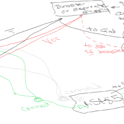
If the Vcc of the adapter is hooked to the 5V of the Mayfly; it’s powered at 5V and has 5V TTL and you’re risking frying you’re Mayfly’s processor. Don’t do that. Use 3.3V or 3.3V switched for the adapter. Use >5V for the sensor.
On their website, Yosemitech still lists the DO sensor as 6-12V and turbidity at 5-12V. So their range mostly overlaps. In real life, I remember the DO sensor actually responding at only 5V. Both would be very happy with either 6V or 12V supply. If you’re going to try to power everything through boost converters off the Mayfly, you should start with the 3.3V instead of using the Mayfly to boost from 3.3V to 5V and then another stepper to move from 5V to 6 or 12V.
Here’s a really ugly drawing:

 Welcome to EnviroDIY, a community for do-it-yourself environmental science and monitoring. EnviroDIY is part of