Home › Forums › Other Data Loggers › Precise analog voltage measurement using Arduino › Reply To: Precise analog voltage measurement using Arduino
Hey Goodluck
Sounds like you have got the measurement traceability going. The local water company here installed a German ultrasonic meter, on the recommendation of Siemens. So far it seems to be slightly under-reading the water flow compared to the impeller meter I have, but haven’t done any detailed measurements on it. I’m waiting to see if there will be any visibility of the readings to customers (me).
I’m using 12V and 4-20mA on a project. Its a using the commercial Onset U30-C3G with analog interface and reporting in over cellular. It has a WiFi option.
The 4-20mA interface has been very good, accurate and stable signal across the 12bit ADC.
I first tested it with some resistors to see how stable it is.
Our issue was accuracy – we wanted to measure changes of 1/100′ or 0.01′. That limited the dynamic range to 10′ depth of water.
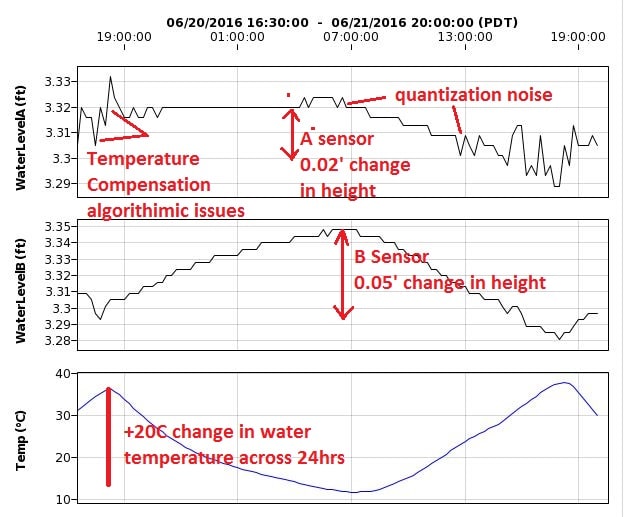
So technically the dynamic range is about 10bit- 2**10=1024. Then you need to take into account digital quantization – the accuracy of the ADC and potential slight drifts that can occur. Temperature drift also needed to be accounted for, and potentially there can be a 20C change in temperature across a day/24hr cycle.
I enclose a graph taken from a snapshot of two sensors tied together over 24hrs of pre-deployment testing in a stable 3.6′ water column. Typically I tested in 0.5′ of water, but wanted to test them at different depth. I believe the noise is coming from the sensors – both sensors are the same type of depth gage, but different responses.
The graph demonstrates the value in doing some acceptance testing in known conditions – in this case level water (except for slight evaporation).
You may want to consider how you can generate a 1/16 gallon flow/leak and then monitor the meters over a couple of weeks.