
4.1 Installing Arduino IDE
- Use the free Arduino IDE (integrated development environment) programming software to program the Mayfly Data Logger. Download the software from Arduino.cc and install the IDE before connecting the Mayfly data logger to your computer.
- NOTE: Windows users will not be able to install this software without administrative privileges.
- If you get a pop-up asking you to install drivers while installing the Arduino IDE, you must allow the drivers to be installed.
- NOTE: Some users have stability issues with the latest version of the Arduino IDE (2.3.7). If you have issues with it, try installing the legacy version (1.8.19) which is available on the same download page. (Scroll down about half-way down the page.)
- Once the Arduino IDE is installed, you will need to add the Mayfly board to the list of available boards. To do this, start the Arduino software, then click on the “File” menu, then “Preferences” and paste the following URL into the box labeled “Additional Boards Manager URLs”:
https://raw.githubusercontent.com/EnviroDIY/Arduino_boards/master/package_EnviroDIY_index.json- If you already have other custom board manager URL’s, extend your list with the EnviroDIY link, separating the URLs with commas.
- In the IDE, click on Tools > Board > Boards Manager. Use the dropdown box to select “Contributed” or search for “EnviroDIY”. You should then see an option for “EnviroDIY ATmega Boards.” Click the Install button to add the EnviroDIY boards to your IDE.
- Now when you click Tools > Board you will see the EnviroDIY Mayfly 1284P listed either at the top or bottom of your list of available boards. Select that and the IDE will be configured to program the Mayfly Data Logger.
4.2 Connecting a Computer to the Mayfly Data Logger
- Plug a USB-C cable into the Mayfly Data Logger, then plug other end of the cable into a free USB port on your computer.
- Turn the Mayfly power switch to the on position. If this is the first time your board has been connected to your computer, wait while the computer recognizes the board and assigns it a COM port number. You might have to allow your operating system to install additional serial port drivers.
- To select the COM port, open the Arduino IDE. Select the COM port assigned to your Mayfly by selecting Tools > Port > COM2 (or COM3, COM4, etc.).
- If no COM ports are available, then your computer either doesn’t “recognize” the Mayfly, meaning that additional drivers need to be installed, or the computer doesn’t “see” the Mayfly because the board isn’t turned on, you have a defective cable, or some other electronic issue.
- Mac computers will usually not need additional drivers installed.
- Windows PCs will sometimes need the driver to be manually updated. You must have administrative privileges on your computer to do this!
- Download the CP210x Universal Windows Driver from the downloads tab on this site and unzip the folder to your desktop.
- Then open your PC’s Device Manager, you should see a device listed (usually under “Ports-COM” or “Other Devices”) with a yellow triangle indicating that it needs drivers.
- Right click on the device and select “Update Driver”.
- When prompted, choose the “Browse my computer for drivers” option and then navigate to the folder you just unzipped on your desktop and click OK. It should then say that the driver was successfully updated.
- Now Windows should recognize your Mayfly board as a serial device and assign it a COM port, and you’ll be able to select it now in the Arduino IDE by selecting Tools > Port > COM2 (or COM3, COM4, etc.).
- In the Arduino IDE, open the Serial Monitor (button in upper right corner of Arduino window or via Tools > Serial Monitor). At the lower right of serial monitor window set the baud rate to 57600. All of the Mayfly boards have been preprogrammed with a sample sketch. This sketch instructs the Mayfly to blink the LEDs and also take some onboard sensor readings and report it to the PC through the Serial Monitor. You should now see that data printed on the Serial Monitor every few seconds.
4.3 Installing Libraries
Preparing sketches (programs) for the Mayfly Data Logger is simplified by the use of libraries: packages of functions that serve as shortcuts when writing sketches. The main library created for environmental logging with the Mayfly Data Logger is ModularSensors. The Modular Sensors library supports dozens of different sensors, including those in the monitoring station. To do so, Modular Sensors requires a number of other smaller libraries to in order to work properly. Managing library dependencies using the Arduino IDE can be tricky. To simplify installation of all of the libraries together, with every release of a new version of Modular Sensors, a zip file is created with the exact required version of each dependency all bundled together. To install everything together:
- Go to EnviroDIY / ModularSensors on GitHub.
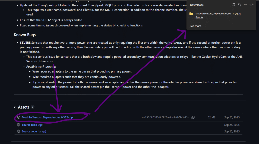
- Look on the lower right hand side of the page for a “Releases” section. Click on the “latest” release. (See the screenshot below, though the version number will change.)

- When you click on the latest release, you will be taken to a page with the notes about the changes and updates on the latest release. Scroll all the way to the bottom of the box with the latest release. At the bottom of the release section, you should see an “Assets” section including a link to a file “ModularSensors_Dependencies_#.##.##.zip.” Click on that link to begin downloading the file. (See the screenshot below, remembering that the version number will be different that that in the screenshot.)
- After downloading the zip file on your computer, navigate to where ever it was stored (likely a “Downloads” folder and up-zip/decompress the file.
- The result of the unzipping should be a bunch of sub-directories. Move all of the sub-directories from the unzipped directory into your Arduino libraries folder. Instructions for finding your libraries folder are here. The final folder structure should be have one subfolder of your libraries folder for each library. You should not have a single “ModularSensors_Dependencies_#.##.##” folder in your libraries folder. You also should not have any bare files in your libraries folder, only folders.
- A correct example (using the default Windows folder location):
C:\Users{your_user_name}\Documents\Arduino\libraries
└ Adafruit ADS1x15
└ … library files …
… lots more libraries in folders …
└ Yosemitech Modbus
└ src
└ … library files …- Once you have copied all the libraries files to your computer, you need to restart the Arduino IDE in order for the software to recognize all the new files, so close and reopen the Arduino IDE.
4.4 Creating and Uploading Sketches
Once the required libraries are installed in the previous step and the IDE has been restarted, the Mayfly Data Logger must then be programmed with a “sketch” telling it what to do before it will work as a data logger. The Arduino IDE allows you to write sketches and then compiles them and sends (uploads) them to the data logger board when complete. There are dozens of tutorials online that
demonstrate how to use the IDE, often using a “blink” or similar sketch. A short guide to Arduino’s IDE is available on their website. The Mayfly board has different pin numbers for LEDs and other parts so generic Arduino board sketches may not work with the Mayfly board without certain modifications.
Another important thing to remember is that the Mayfly board (like all Arduino boards) can only remember one sketch at a time. If you program it with a sketch and then later reprogram it with a new sketch, the Mayfly doesn’t remember anything from the first sketch. There’s also no way to “download” the existing sketch off a Mayfly board if it has already been programmed.
4.5 Setting the Clock
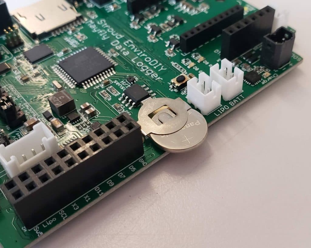
The first step in preparing the Mayfly Data Logger for use as a logger is to set its DS3231 real-time clock. Doing this requires installation of the DS3231 library, which is included in the required libraries as described above. Before setting the clock, slide a size CR1220 battery (available at most pharmacies and hardware stores or online) into the RTC battery holder. The “+” side of the battery goes up. (Usually the lettering is on the “+” side.) This battery will only power the memory of the clock chip and will allow the clock to keep time for several years, even if the rest of the board is not powered.
A sketch for setting the clock is one of the examples in the DS3231 library on GitHub. Follow the steps in the ReadMe section. The PCsync sketch will set the time at GMT. There are alternative techniques that will allow different time zones.
The recommended approach to setting the clock on your Mayfly Data Logger can also be found on GitHub. Or if your data logger will be equipped with a cellular or WiFi module and will have an active SIM card or WiFi access, then you can skip this step of manually setting your RTC clock because (if using one of our recommended data logger sketches) your Mayfly board will connect to an internet time server and set the RTC right after booting up. If your Mayfly will not have internet access, or you’ll be using a different sketch, you’ll need to manually set the clock as described below.
Follow the steps in the ReadMe section that states, to synchronize the clock:
- Ensure that you have the EnviroDIY_DS3231 library installed in your IDE. (It will be if you installed all of the libraries in the steps in section 4.3.)
- Plug the Mayfly board into your computer and make sure it is visible to your system. You may have to wait for your OS to install additional hardware drivers. Select the correct COM port from the Tools menu. Open the Arduino IDE’s Serial Monitor and select the correct baud rate (usually 57600).
- Open the adjust.ino sketch in your IDE. Scroll to line 11. Modify the text in line 11 to be a date and time about 2 minutes in the future. Note: you should program the clock in UTC time and not local time if you will be using the recommended sketched that transmit data to MonitorMyWatershed because they are expecting the time from the Mayfly to be in UTC. Also note that in the sketch, the days of the week start counting at 0, so Sunday is day 0, Monday is day 1, etc. Upload the sketch to your Mayfly. You should now see the date and time being printed to the Serial Monitor every second, and it started counting from that future timestamp you entered in the sketch. Every time you restart the Mayfly board, it will reset the onboard RTC with that same time. We set it in the future to give us a little time to find the right time and get ready for the synchronizing procedure. Keep the Serial Monitor open throughout this entire process. Anytime you close it and re-open the Serial Monitor, it will restart the board and thus restart the clock.
- Open the Official U.S. Time website in a web browser or look at another clock (like a cell phone) displaying the correct time. The time.gov website has a handy UTC clock displayed in the upper righthand corner of that page. When the current time on your phone or the website is about 2 seconds before the the time that you entered in the sketch, hit the tiny RESET button on the Mayfly board. This will restart the sketch and also restart the Mayfly’s RTC with the correct time.
- The time being printed to the Serial Monitor every second should match your phone and the time.gov website. If it doesn’t, you may need to repeat steps 3 and 4 several times to get the time right. It’s okay if it’s a few seconds off, the goal is to get the RTC time fairly close to the actual time.
- Important: you must program a different sketch onto the Mayfly now before proceeding, otherwise the RTC will be revert to the hard-coded time listed in line 11 anytime the Mayfly is reset or restarted or if you close and re-open the Serial Monitor. We recommend using the now.ino sample sketch from that same DS3231 library because it will print the date and time to the screen every second, which will help verify that your clock was set correctly with the adjust.ino sketch.