Home › Forums › Environmental Sensors › RS485/Modbus RTU Transducers › Reply To: RS485/Modbus RTU Transducers
https://en.wikipedia.org/wiki/OSI_model
For the nanolevel it specif
https://en.wikipedia.org/wiki/OSI_model
For the nanolevel it specifies physical layer as RS485 (for other equipment it may be the customer SDI-12)
For Keller products the modbus binary “data link layer” there is a document “Keller comm_protocol_series 30 V3.4 2015Oct.pdf”
http://www.kelleramerica.com/manuals-and-software/manuals/series30%20comm_protocol_e.pdf
Every manufacturer that is claiming an open interface, or expects their equipment to network, should supply a description of their implementation of a protocol.
The modbus protocol concept is fairly simple one. IMHO the modbus language is fairly archaic and easier to think of it as a query /response protocol than to try and use the older language associated with register read/writes.
The manufacturers manual is the starting point for understanding what is needed to get data from the device, and there is no such thing as a standardization process for modbusm
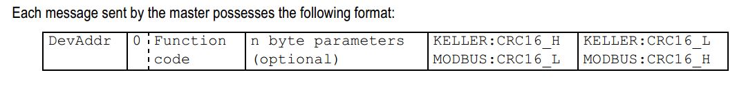
<DevAddr> <FunctionCode> <n byte payload …> <KellerCrc16_H> <KellerCrc16_L>
For Keller a significant difference is that they switch the CRC-16 bytes around from standard modbus !!!
I process this with two functions
rs485crc16add(..) rs485crc16chk(..)
were CRC16calc() does all the magic work with a standard CRCTable
See
https://bitbucket.org/neilh20/nuttapps/src/5315c5ee8f8fcdb7d5dd69989b499194fc30a034/examples/ae/aelog/ae_mdm_phy.c?at=work_ensy1b&fileviewer=file-view-default
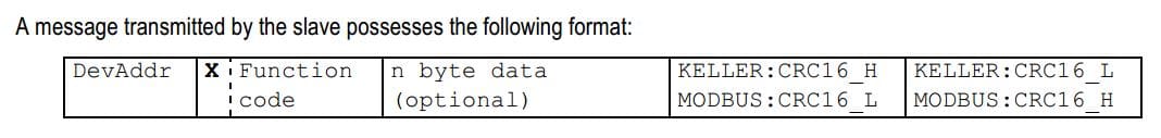
Now the controlling requestor “master” tx
and the device “slave” responds (looks pretty similar – but the payload is the significant part.
For the first time testing of the protocol, the objective is just to ensure the mechanics are good.
Out 01 03 00 04 00 01 C5 CB – Read Address 4, 1 registers – which is read level
Resp 1 3 2 0 0 B8 44 – Std Crc – result is 0
(or use some of the examples in the manual, though its a bit confusing they don’t all apply to every instrument)
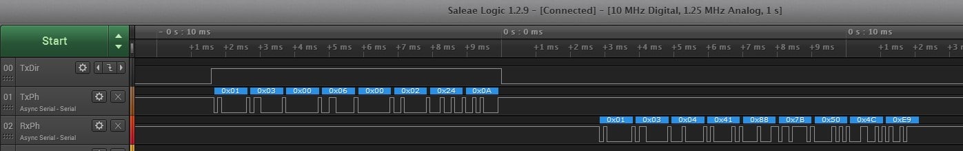
Another example – read register 6 (temperature), 2words and interpret the two words as floating point IEEE754
Send 01 03 00 06 00 02 24 0A
Rx 01 03 04 41 88 7B 50 4C E9
Payload: 41 88 C9 48
h-schmidt.net/FloatConverter/IEEE754.html says 17.0 (and the units are C)
A Saelig Logic Analyzer trace of this is