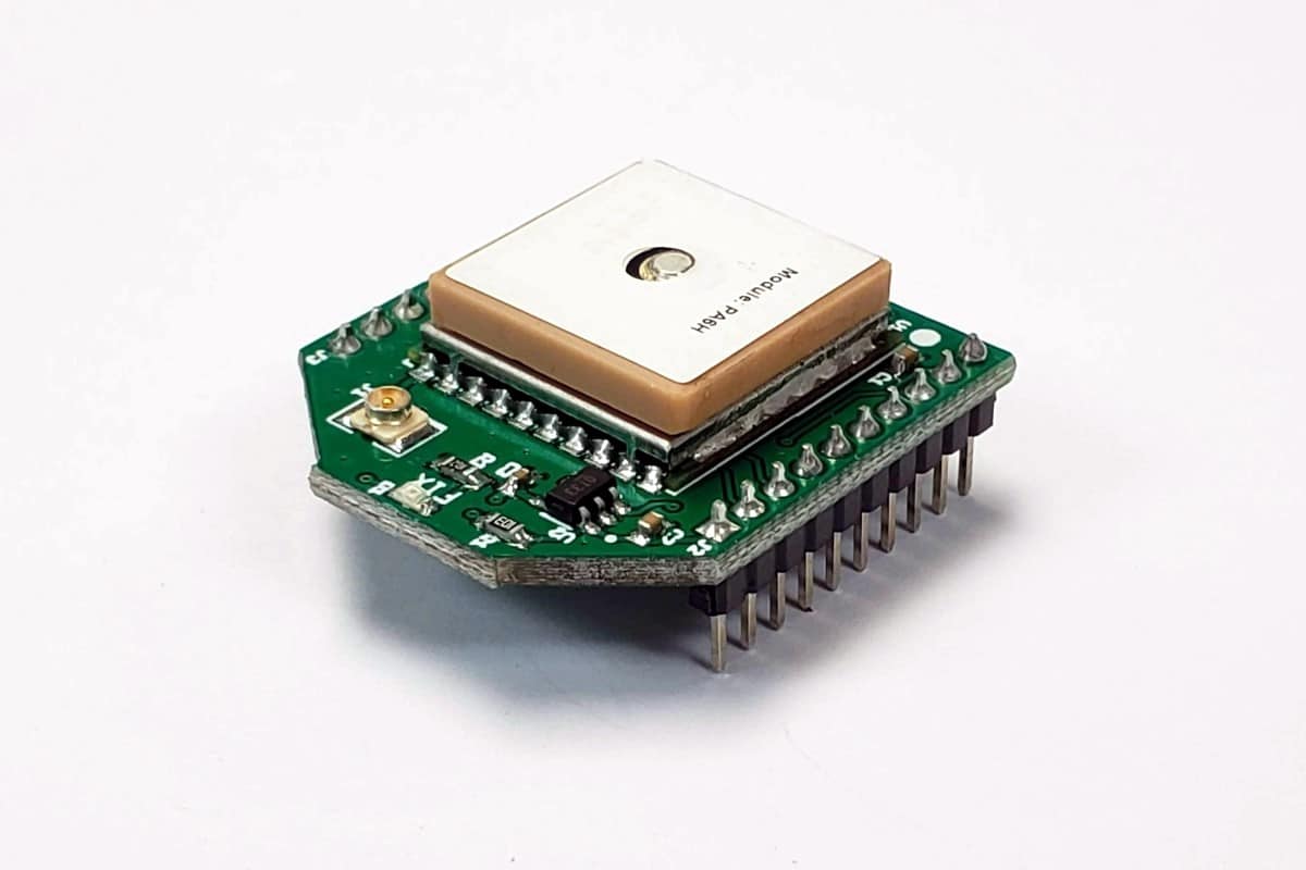
The EnviroDIY GPSbee is an easy way to add GPS capability to any device that is compatible with the standard Bee footprint. It’s built around the popular MTK3339 GPS module and can be powered with either 3.3v or 5v, and it uses around 20ma when in operation. The module has its own built-in antenna, but the board also has a separate u.fl jack for adding an optional external passive antenna.

There are 2 solder jumpers on the back of the GPSbee. The default setting for both is “open” so you’ll need to solder a blob of solder across either of them if you want to “close” them. Closing SJ1 allows the green “FIX” LED to blink while the board is acquiring a fix (it goes out once you get a fix, so the LED only shows you when the module is trying to get a fix). The other jumper (SJ2) selects how you want to control the supplied power for the GPSbee. The default setting (open) is for the GBSbee to be OFF all the time and only comes on if you set Bee socket pin 9 high (which is controlled by Mayfly pin D23). So if you are using an EnviroDIY Mayfly board with the GPSbee, your Mayfly code can turn the GPSbee ON or OFF as needed, depending on what the rest of your code is doing. However, if you’re using the GPSbee with something other than a Mayfly, or you want the GPSbee to be on anytime power is applied to the Vcc pin (pin 1), just short out the SJ2 “ALWAYS ON” jumper and the GPSbee will stay on.
The EnviroDIY GPSbee uses the same series of GPS unit that’s used on the Adafruit Ultimate GPS board, so if you’re looking for code examples, the easiest thing is to use Adafruit’s library that they guarantee that it works with that module: https://github.com/adafruit/Adafruit_GPS
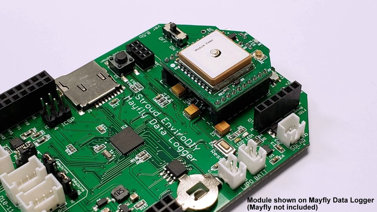
If you use the GPSbee with an EnviroDIY Mayfly, just plug the GPSbee into the Bee headers on the Mayfly and it’ll be connected to the Mayfly’s second hardware serial port (Serial1). You can use the following sketch from Adafruit’s library exactly as-is without any changes necessary: https://github.com/adafruit/Adafruit_GPS/tree/master/examples/GPS_HardwareSerial_Timing
If you didn’t short out the “ALWAYS ON” solder jumper, you’ll need to add the following two lines at the beginning of your “void Setup” function:
pinMode(23, OUTPUT);
digitalWrite(23, HIGH);
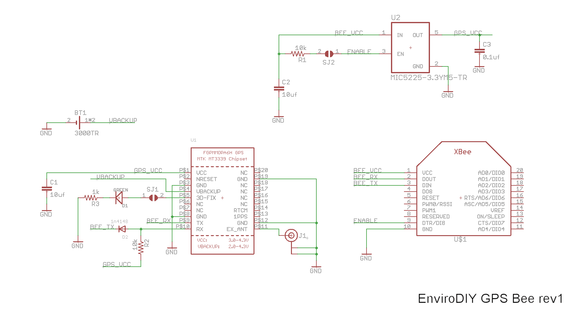
If you’re using the GPSbee with anything other than an EnviroDIY Mayfly, you’ll need to figure out the proper wiring for your device or adapter. The GPSbee only needs connections on 4 pins of the Bee header (or 5 if you want to control the power as mentioned above). Bee Pin 1 is Vcc, Pin 10 is Ground, and pin 2 and 3 are serial RX/TX. See the schematic below for the wiring details of the EnviroDIY GPSbee.