
To access a printable PDF version of the EnviroDIY Troubleshooting Quick Guide please click the following link: EnviroDIY Monitoring Station Troubleshooting Quick Guide. The troubleshooting quick guide is designed to be printed to provide troubleshooting tips while in the field. Further explanations can be found in the text below.
4.1 Battery Dies
When logger battery level goes below ~3.4 V the data logger will cease to operate, so the logger is programmed to stop transmitting data to the website at 3.55v, however data will still be saved to the microSD card until it gets below 3.4v.
- Check solar panel and red wire outside the logger box.
- Ensure no corrosion or excess moisture is seen on the Mayfly logger board.
- Check that no insect or rodents have chewed wires or occupied the inside of the enclosure.
- Check solar panel orientation, look at the live data, has it been charging or slowly dying-canopy cover can change and adjustments may need to be made.
- If several lights are constantly lit on the Mayfly, or you see no lights during the sampling period (usually set to every 5 minutes), then the logger program may have “frozen” and caused an excess drain on the battery.
- For given light conditions you may need to upgrade to a larger battery or solar panel or both.
- Occasionally a battery pack will fail after about 2 or 3 years, usually because it was exposed to excess moisture that causes rust and damage inside the battery pack. Replace it with a new one and properly dispose of the old pack.
4.2 Data From the Real-Time Feed Stops
- Cycle the logger power by turning the main Mayfly power switch ON/OFF.
- Check to see if the data are being recorded on the SD card, and thatdata on the card are being recorded every 5 minutes. When you turn the logger on (with a working battery), you’ll see the green light briefly flash, then the red and green lights will blink back and forth 5 times really quickly (less than a second). Then everything will be dark, except for the yellow CHARGE light which indicates the solar panel is charging the battery. Depending on the logging sketch running on the Mayfly, you may see it start up and blink various lights as it tests the sensors and cell connection and verifies the RTC timestamp. Once the test is done, all lights should go off (except for the CHARGE light if charging). If you stick around until the even 5 minute intervals (3:05, 3:10, 3:15, 3:20), you’ll see the green light turn on along with a red light in the far corner by the sensor jacks (indicating the sensors are powered). After about 10 seconds, the sensor power red light goes off, then you’ll see the small lights on the cellular board blinking. It’ll do this for a little bit as it’s establishing a connection. Once it gets a valid cell connection and sends the data, the cell board blinks rapidly for a few seconds, then all lights go out and the system is now asleep. If you aren’t seeing this sort of behavior on the 5-minute intervals, then something is wrong. But looking at the data on the card will also tell you if it’s logging properly and what the battery voltage is. There may be times where the battery is too low to power the cell board, but the Mayfly will still be recording data on the card, so that’s why we need to see what’s being recorded there.
- Loggers may “lock up” and stop connecting to the cellular network after a period where the cell network was unavailable or had extremely low signal strength, or other connection issues. The only way to get them to “reconnect” is to just cycle the power on the logger. Anytime you see a logger go offline and the battery voltage wasn’t too low (below 3.55 V) the last time the network “heard” from the logger, then someone should just simply go to the station and cycle the power using the power switch on the Mayfly. There’s absolutely nothing wrong with cycling the power anytime the stations acts strange. You should also swap out the memory card when you do this to see if the station has been recording data on the card during the cellular outage, or if for some reason the entire logger was paused.
- Battery has died (due to issues discussed above), replace battery, possibly with larger model.
- Circuit board has for some reason shorted. Possible reasons for shorting:
- Cell module “antenna” has contacted the Mayfly board. This antenna is a small board with a wire attached to the cell Xbee board (red arrow in photo below). If the antenna comes in direct contact with the Mayfly board it will damage the board. The standard location for this antenna is outside the logger board case. If this antenna comes in direct contact with the Mayfly board it will most likely damage the board and a replacement will be required.
- Water has entered the logger box and contacted the Mayfly Data Logger board. Although the logger boxes are water tight there are ways in which water may enter including: bent hinges of the logger box door, defective logger box seals, debris (e.g.,grass, sticks) between the seals. If water does enter the box a dessicant pack can be used to dry it out, however, unless the source of water entry is dealt with it is likely that the Mayfly board will be damaged with repeated water exposure.
- Cell signal may have been lost through a power outage, non-payment on your account, or cell tower issues. If you have ruled out power outage, contact your provider.
- Hologram SIM card data plan has not been paid. If data stop on the same day of the month that the plan was last renewed this is likely the problem. In this case money would just need to be added to the account, at which point data should begin transmitting again. Hologram will email a warning 24 hours prior to expiration.
4.3 Invalid Sensor Readings
If a station starts reporting -9999 for one or more parameters, then that indicates the Mayfly logger is not receiving any data from the sensor. (The -9999 value is a placeholder that the Mayfly stores in the data record to indicate that it did not receive a valid data value from the sensor). This usually means the sensor or cable is damaged, so someone should visit the station as soon as possible to check the following things:
- Check sensor wires from sensor to logger box, make sure it has not been severed or damaged
- Open the logger case and check that the sensor connections are firm and that there is no corrosion on the Mayfly board or the sensor adapter board.
- Cycle the logger power by turning the Mayfly power switch ON/OFF.
If you’re working with a Meter Hydros 21 CTD sensor, then having a Zentra ZSC bluetooth module is extremely useful because you can use an app on your phone to connect directly to the sensor and see the raw values
4.4 Brown Varnish on Turbidity Sensor
Most of the optical sensors have this issue after being deployed for a few years or more. It’s a chemical reaction between the sensor and some of the dissolved minerals in certain streams that collects on the sensor over time. If excess fouling obscures the optical sensor window, chemical cleaning of the sensor is required, using a series of weak oxalic acid treatments.
If station owners in the Delaware River Watershed Initiative (DRWI) program notice excess fouling on their turbidity sensor, they should contact someone from the Stroud Center team and a maintenance visit will be scheduled for proper cleaning of the sensor.
Other optical sensors require different maintenance and cleaning routines, so refer to the manufacturers suggested protocols for those procedures. Anyone cleaning an optical sensor window should use care to not scratch the window or use a chemical that would interact with the sensor materials, or permanent damage may occur.4.5 Erratic Depth Measurements
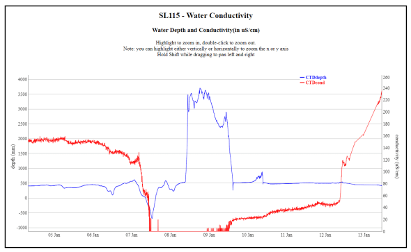
From looking at the graph, it appears that the pressure portion of the CTD sensor is damaged. You can see when it froze because the conductivity went to 0 overnight, meaning there was no liquid water around the sensor anymore, and then the next day the pressure rose dramatically and said there was 3.5 meters of water. Ever since then, the pressure signal is a combination of depth plus water temperature, because when these sensors fail, the temperature-compensating part of the sensor gets magnified and you start seeing big “pressure” changes that exactly mirror the water temperature readings. There’s no way to look at a sensor to assess freeze damage, so you’ll just have to remove it and replace it with a new one.
4.6 Highly Variable Measurements
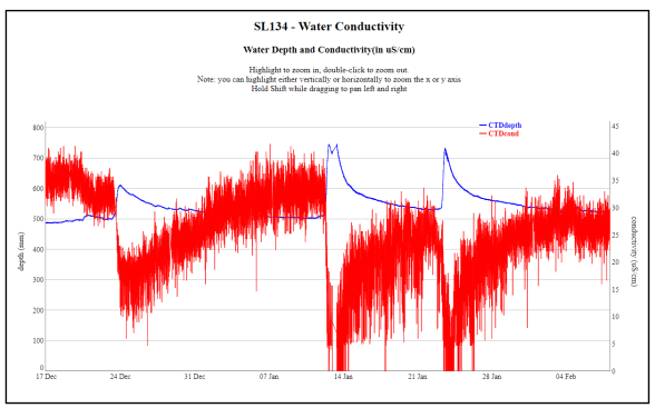
Sometimes a CTD sensor will show unusual “noise” on one or more parameters. Sometimes it starts gradually, other times it can happen quickly, usually during a storm or other damaging event. They will often get noisier over time, therefore, a replacement sensor will probably be in needed. Sometimes a sensor will perform properly for months or years before behaving erratically, so if you properly clean a noisy sensor and it still behaves this way, then it’s time to replace it.
4.7 Spiky Conductivity Measurements
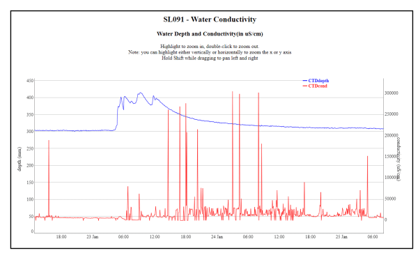
CTD sensor malfunction; replacement sensor needed
4.8 Rapid Change in Depth
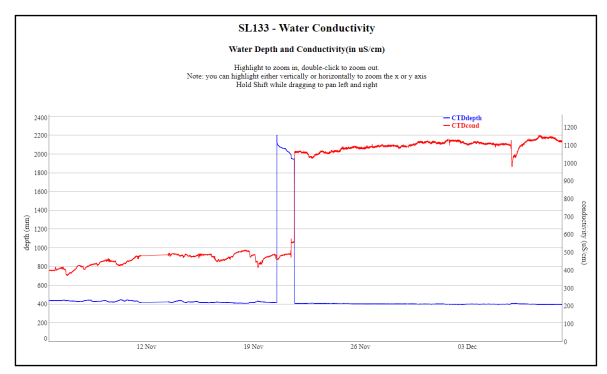
A rock was lodged in the CTD sensor and pressing against the pressure transducer. That rock lodged in the sensor also somehow caused the conductivity to read abnormally low for some reason. After the rock was removed, conductivity was tested with three separate meters and each read about 1100 μS/cm. So all of the conductivity dated during the period with the inaccurate depth is probably false. This was a unique situation and is not observed regularly.